 |
|||
|
|
|||
|
|
|||
| ||||||||||
|
|
 TM 5-2410-237-23
BLADE CONTROL LEVER AND LINKAGE REPLACEMENT - CONTINUED
0207 00
REMOVAL
WARNING
Do NOT remove hydraulic tank filler cap or disconnect or remove any hydraulic system line or fitting
unless hydraulic system pressure has been relieved. Hydraulic system pressure can be over 2500 psi (17,237
kPa), even with engine and pump OFF. To relieve pressure, lower all hydraulic attachments to the ground
and shut down engine. Move control levers through all operating positions, then SLOWLY loosen hydraulic
tank filler cap. After maintenance, tighten all connections before applying pressure. Escaping hydraulic
fluid under pressure can penetrate the skin, causing serious injury or death.
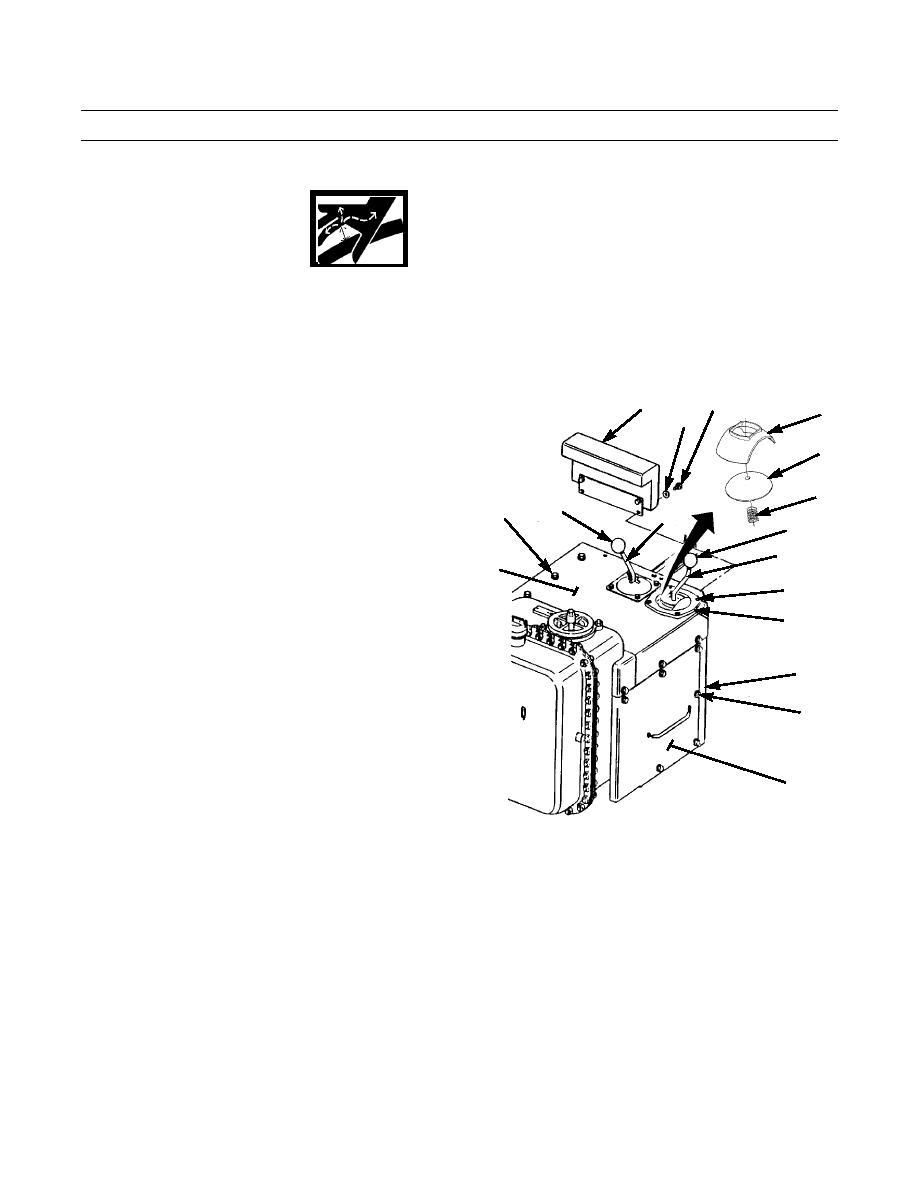
1.
Remove two capscrews (1), washers (2) and armrest
1
3
17
(3) from control console (4).
2
2.
Remove knob (5) from blade control lever (6).
18
3.
Remove knob (7) from ripper or winch control lever
(8) (whichever applies).
19
4.
Remove four screws (9) and cover (10) from cover
12,13
7
8
(11).
5
5.
Remove nine capscrews (12), washers (13) and cover
6
11
(11) from control console (4).
6.
Remove six capscrews (14), washers (15) and plate
9
(16) from front of control console (4).
10
7.
Remove guide (17), dome (18) and spring (19) from
blade control lever (6).
4
14,15
16
387-641
0207 00-2
|
|
Privacy Statement - Press Release - Copyright Information. - Contact Us |
