 |
|||
|
|
|||
|
|
|||
| ||||||||||
|
|
 TM 5-2410-237-23
RIPPER CONTROL VALVE REPLACEMENT - CONTINUED
0206 00
INSTALLATION - CONTINUED
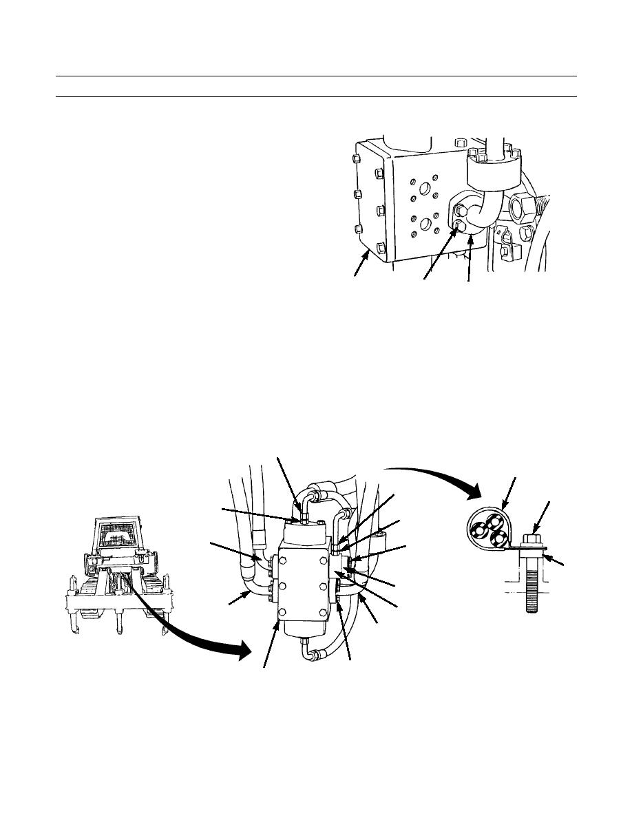
7.
Install new O-ring (32) to elbow (31). Install elbow to
ripper control valve (6) with four washers (30) and
capscrews (29).
387-617
6
29,30
31,32
8.
Install new O-ring (28) to adapter (26).
9.
Install new O-ring (27) to line (25). Install line and adapter (26) to ripper control valve (6) with two split flanges (24),
four washers (23) and capscrews (22).
10.
Install new O-ring (19, 20 and 21) to each of three lines (16, 17 and 18). Connect each line to ripper control valve (6)
with two split flanges (15), four washers (14) and capscrews (13).
11.
Install two adapters (9 and 10) to ripper control valve (6).
12.
Install new O-rings (11 and 12) in each of two lines (7 and 8) and connect oil lines to adapters (9 and 10).
13.
Connect three oil lines to final drive case with spacer (5), clamp (4), washer (3), new lockwasher (2) and capscrew (1).
7,11
4
8,12
1,2,3
9
10
17,20
22,23,24
5
25,27
18,21
26,28
16,19
13,14,15
387-616
6
14.
Check level of oil in hydraulic tank. Refill tank and bleed air from system, as required (WP 0225).
15.
Operate machine and check ripper for proper operation and leaks (TM 5-2410-237-10).
END OF WORK PACKAGE
0206 00-6
|
|
Privacy Statement - Press Release - Copyright Information. - Contact Us |
