 |
|||
|
|
|||
|
|
|||
| ||||||||||
|
|
 TM 5-2410-237-23
RIPPER CONTROL VALVE REPLACEMENT - CONTINUED
0206 00
REMOVAL - CONTINUED
14.
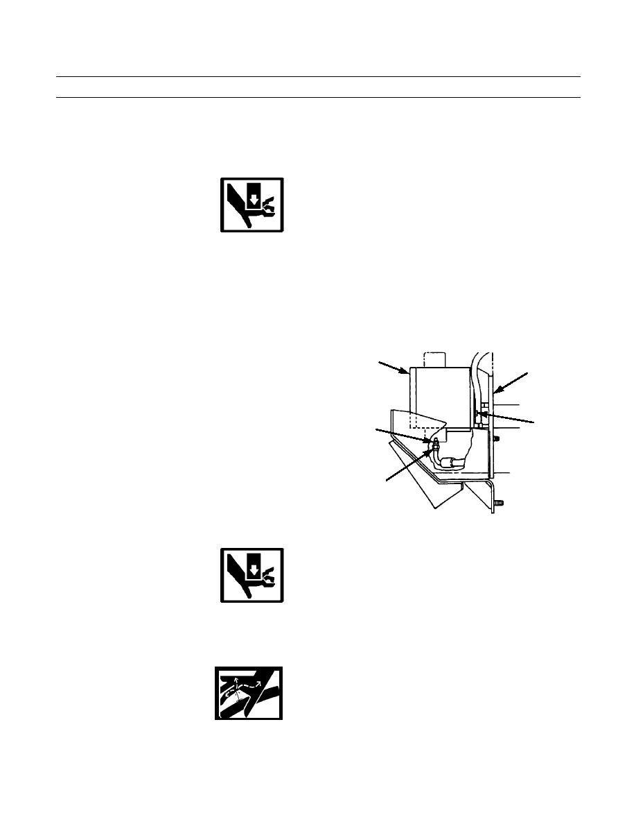
Disconnect pilot oil line (44) from adapter (45) at bottom of ripper control valve (6). Remove O-ring (46) from line. Dis-
card O-ring.
15.
Remove adapter (45) from ripper control valve (6).
WARNING
Use extreme caution when handling heavy parts. Provide adequate support and use assistance during pro-
cedure. Ensure that any lifting device used is in good condition and of suitable load capacity. Keep clear of
heavy parts supported only by lifting device. Failure to follow this warning may result in death or injury to
personnel.
NOTE
Ripper control valve weighs 55 lb (25 kg).
16.
Attach a nylon sling and a suitable lifting device to
6
ripper control valve (6) to take weight off capscrews
49
(47) during removal.
17.
Remove four capscrews (47), washers (48) and ripper
control valve (6) from mounting bracket (49).
47,48
45
44,46
387-620
INSTALLATION
WARNING
Use extreme caution when handling heavy parts. Provide adequate support and use assistance during pro-
cedure. Ensure that any lifting device used is in good condition and of suitable load capacity. Keep clear of
heavy parts supported only by lifting device. Failure to follow this warning may result in death or injury to
personnel.
WARNING
Ensure all sealing surfaces on valve and hoses are clean and dry before installation. Contamination of
hydraulic system could result in premature failure.
0206 00-4
|
|
Privacy Statement - Press Release - Copyright Information. - Contact Us |
