 |
|||
|
|
|||
|
|
|||
| ||||||||||
|
|
 TM 5-2410-237-23
RIPPER CONTROL VALVE REPLACEMENT - CONTINUED
0206 00
REMOVAL
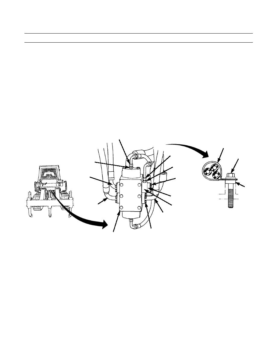
1.
Remove capscrew (1), lockwasher (2), washer (3), clamp (4) and spacer (5) to release three oil lines from final drive
case above ripper control valve (6). Discard lockwasher.
2.
Disconnect two oil lines (7 and 8) from two adapters (9 and 10). Remove two O-rings (11 and 12) from lines. Discard O-
rings.
3.
Remove two adapters (9 and 10) from ripper control valve (6).
4.
Remove four capscrews (13), washers (14) and two split flanges (15) from each of three lines (16, 17 and 18). Discon-
nect lines from ripper control valve (6).
5.
Remove O-rings (19, 20 and 21) from each line (16, 17 and 18). Discard O-rings.
6.
Remove four capscrews (22), washers (23), two split flanges (24) and disconnect line (25) from adapter (26). Remove
O-ring (27) from line. Discard O-ring.
7.
Remove adapter (26) and O-ring (28) from ripper control valve (6). Discard O-ring.
7,11
4
8,12
1,2,3
9
10
17,20
22,23,24
5
25,27
18,21
26,28
16,19
13,14,15
387-616
6
0206 00-2
|
|
Privacy Statement - Press Release - Copyright Information. - Contact Us |
