 |
|||
|
|
|||
|
Page Title:
WINCH CONTROL LEVER AND LINKAGE ADJUSTMENT |
|
||
| ||||||||||
|
|
 TM 5-2410-237-23
WINCH CONTROL LEVER AND LINKAGE ADJUSTMENT
THIS WORK PACKAGE COVERS
Adjustment
INITIAL SETUP
Materials/Parts - Continued
Applicable Configuration
Tractor with winch
Nut, self-locking (6 and 18)
Tools and Special Tools
Pin, spring
Tool kit, general mechanic's (Item 122, WP 0250
Equipment Condition
Gage, pressure, dial indicating, 0-600 psi (Item 30,
Tractor parked on level ground (TM 5-2410-237-
10)
Materials/Parts
Engine OFF and cool (TM 5-2410-237-10)
Lockwasher (3 and 14)
ADJUSTMENT
1.
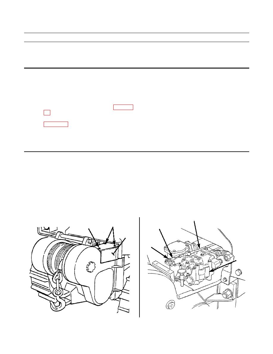
Remove two capscrews (1), capscrews (2) and four lockwashers (3) from cover (4). Remove cover. Discard lockwash-
ers.
2.
Remove capscrew (5) and self-locking nut (6) from rod end (7) and lever at winch control valve (8). Discard self-lock-
ing nut.
3.
Adjust control cable (9) so that distance between rod end (7) and end of threads on control cable is 0.50 in. (12.7 mm).
4.
Install rod end (7) on lever and secure with capscrew (5) and new self-locking nut (6). Tighten nut securely against rod
end.
9
1,3
7
2,3
4
5,6
8
387-388
387-387
|
|
Privacy Statement - Press Release - Copyright Information. - Contact Us |
