 |
|||
|
|
|||
|
|
|||
| ||||||||||
|
|
 TM 5-2410-237-23
WINCH ASSEMBLY REPLACEMENT - CONTINUED
0180 00
INSTALLATION
NOTE
Prior to installation, ensure all traces of paint or rust have been removed from mounting surfaces of
winch and tractor and from mounting studs.
Wipe clean all retaining ring and O-ring grooves in components.
Lightly coat all new O-rings with clean oil before installation.
1.
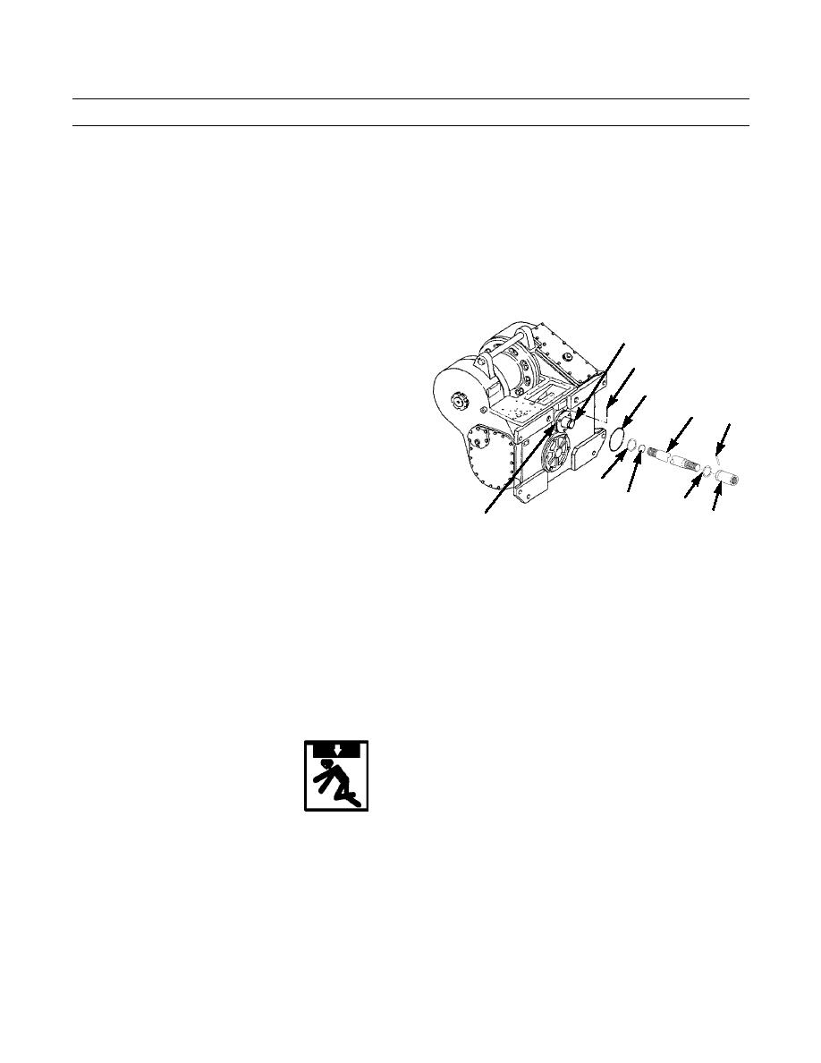
Install new O-ring (32) on drive shaft (18).
2.
Install new O-ring (30) on coupling flange (31).
3.
Temporarily install retaining ring (27) onto end of
28
winch coupling (28) and rotate coupling with hole
29
straight up. Keep bottom of retaining ring to hold pin
(29) in position.
30
18
4.
Insert drive shaft (18) into winch coupling (28), align
25
holes and install pin (29). Retain pin by sliding retain-
ing ring (27) into groove in winch coupling (28).
5.
Lightly lubricate, then temporarily install retaining
27
ring (24) on groove end of coupling (26). Do NOT
32
24
install retaining ring in groove at this time.
26
31
6.
Install coupling (26) on drive shaft (18), align holes
and install pin (25). Retain pin by sliding retaining
387-473
ring (24) into groove in coupling (26).
NOTE
Use a tap to chase and clean threaded holes in bosses to which chain end links are attached.
7.
Attach lifting link with 3/4-10 x 1-1/2 in. bolt in threaded boss (1) on each side of winch (2).
8.
Remove nine capscrews (22), lockwashers (21), round cover (20) and gasket (19) from opening in final drive case at
rear of tractor. Discard gasket and lockwashers.
9.
Install two new O-rings (23) on top inner studs (13).
WARNING
Use extreme caution when handling heavy parts. Provide adequate support and use assistance during pro-
cedure. Ensure that any lifting device used is in good condition and of suitable load capacity. Keep clear of
heavy parts supported only by lifting device. Failure to follow this warning may result in death or injury to
personnel.
NOTE
Winch assembly weighs approximately 3600 lb (1634 kg).
10.
Attach a suitable three-point lifting device to lifting link on each side of winch (2) and to bar (14).
0180 00-4
|
|
Privacy Statement - Press Release - Copyright Information. - Contact Us |
