 |
|||
|
|
|||
|
Page Title:
WINCH HYDRAULIC SYSTEM - CONTINUED. |
|
||
| ||||||||||
|
|
 TM 5-2410-237-23
WINCH THEORY OF OPERATION - CONTINUED
0178 00
WINCH HYDRAULIC SYSTEM - CONTINUED.
14
3
15
8
9
4
2
5
6
10
1
7
13
16
11 12
17
387-537
24
18
21
25
19
22
23
20
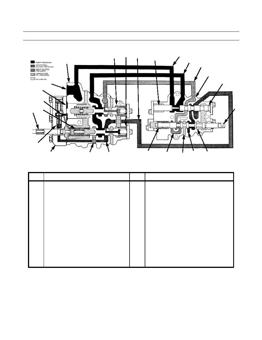
Table 1. Control System Oil Flow Schematic (REEL OUT Position).
Key
COMPONENT
key
COMPONENT
14
1
Supply Port
Spool
2
15
Body of Pressure Control Valve
Oil Passage
3
16
Oil Passage
Spool
4
17
Oil Passage
Sequence Valve
5
18
Oil Passage
Cover
6
19
Body of Valve for Selection of Direction
Oil Line
7
20
Load Piston
Oil Passage
8
21
Spool
Centering Spring
9
22
Stop
Fill Chamber for Input Clutch
10
23
Spool
Drain
11
24
Coupling
Fill Chamber for Right Side Directional Clutch
12
25
Spring Assembly
Fill Chamber for Left Side Directional Clutch
13
Oil Passage
5.
REEL IN Position. The sequence of operation for REEL IN is identical to that for REEL OUT. The only difference is in
control lever throw, which results in spool (16) being moved into valve body (6). Chamber (25) fills instead of chamber
(24). Chamber (25) is connected to the left directional clutch and winch drum rotation will reverse.
0178 00-4
|
|
Privacy Statement - Press Release - Copyright Information. - Contact Us |
