 |
|||
|
|
|||
|
Page Title:
SEAT AND SEAT BASE ASSEMBLY INSTALLATION |
|
||
| ||||||||||
|
|
 TM 5-2410-237-23
SEAT, SEAT BASE ASSEMBLY AND SEAT BELT REPLACEMENT - CONTINUED
0172 00
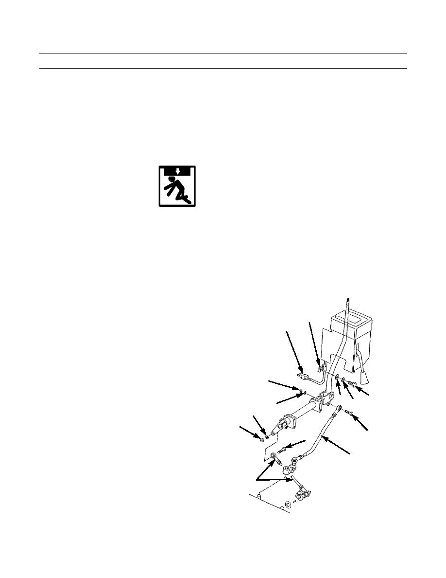
SEAT AND SEAT BASE ASSEMBLY INSTALLATION
1.
Position transmission control box assembly (55) on left side of seat base assembly (5) and install capscrew (53) and
washer (54).
2.
Position shield (52) in position and install capscrew (46), washer (47), new lockwasher (49) and nut (48). Install cap-
screw (50) and washer (51).
3.
Position linkage assembly (45) on seat base assembly (5) and install four capscrews (41 and 42) and new lockwashers
(43 and 44).
4.
Align holes in selector lever (39) and fork (40) and install capscrew (38) and new self-locking nut (37).
WARNING
Use extreme caution when handling heavy parts. Provide adequate support and use assistance during pro-
cedure. Ensure that any lifting device used is in good condition and of suitable load capacity. Keep clear of
heavy parts supported only by lifting device. Failure to follow this warning may result in death or injury to
personnel.
NOTE
Seat base assembly weighs 72 lb (33 kg).
5.
Attach nylon slings and suitable lifting device and lift seat base assembly (5) into position on tractor. Leave lifting
equipment attached.
NOTE
Do NOT tighten seat base mounting cap-
32
screws until all have been installed.
20
6.
Secure seat base assembly (5) on left side with three
capscrews (35) and washers (36).
7.
Install six capscrews (33) and washers (34) through
right side of seat base assembly (5).
8.
Tighten nine mounting capscrews (33 and 35).
21
9.
Install capscrew (23), new lockwasher (26) and nut
(25) to secure transmission gear selection linkage rod
(28).
29
31
30
22
10.
Install capscrew (23), new lockwasher (22) and nut
26
(21) to secure transmission direction linkage rod (24).
25
11.
Connect two backup alarm wires (20) to wiring har-
ness.
23
27
12.
Install clamp (32) on wiring with capscrew (29), new
lockwasher (30) and washer (31).
24
28
387-408
0172 00-5
|
|
Privacy Statement - Press Release - Copyright Information. - Contact Us |
