 |
|||
|
|
|||
|
Page Title:
STEERING BRAKE RELIEF VALVE REPLACEMENT |
|
||
| ||||||||||
|
|
 TM 5-2410-237-23
STEERING BRAKE RELIEF VALVE REPLACEMENT
THIS WORK PACKAGE COVERS
Removal, Cleaning and Inspection, Installation
INITIAL SETUP
References
Tools and Special Tools
TM 5-2410-237-10
Tool kit, general mechanic's (Item 122, WP 0250
Shop equipment, general purpose repair (Item 106,
Equipment Condition
L.H. brake hydraulic control assembly removed
Materials/Parts
Oil, lubricating (Item 26, WP 0249 00)
Rag, wiping (Item 29, WP 0249 00)
REMOVAL
4
NOTE
This valve is located next to brake actuat-
ing mechanism on left side of machine
only.
1.
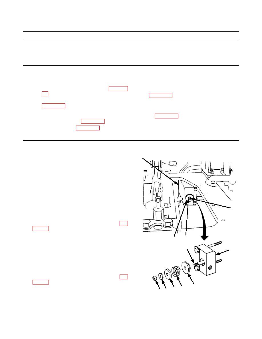
Remove nut (1) and washer (2) from pin (3) in block
assembly (4).
2.
Remove spring retainer (5), spring (6) and valve (7)
from block assembly (4).
3
CLEANING AND INSPECTION
1.
Wipe all parts clean and dry IAW instructions in WP
2.
Inspect parts for wear and replace if necessary.
1
2
INSTALLATION
3
4
1.
Apply a film of clean lubricating oil on valve (7) and
install valve in block assembly (4) over pin (3).
2.
Install spring (6) and spring retainer (5) on valve (7)
over pin (3).
3.
Install washer (2) and nut (1) on pin (3).
4.
Install L.H. brake hydraulic control assembly (WP
387-287
7
5.
Test drive and check steering for proper operation
6
5
1 2
(TM 5-2410-237-10).
END OF WORK PACKAGE
|
|
Privacy Statement - Press Release - Copyright Information. - Contact Us |