 |
|||
|
|
|||
|
|
|||
| ||||||||||
|
|
 TM 5-2410-237-23
STEERING BRAKE HYDRAULIC CONTROL ASSEMBLY MAINTENANCE - CONTINUED
0151 00
INSTALLATION - CONTINUED
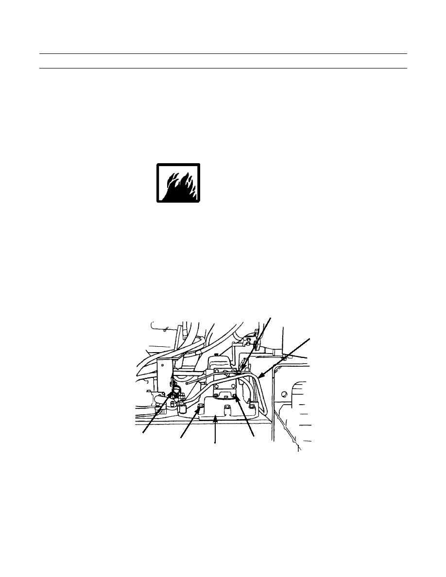
5.
Install 16 capscrews (48), washers (49) and two spacers (50) around edge of hydraulic control (12). Tighten capscrews
to 100 lb-ft (136 Nm).
NOTE
If tractor has ripper attachment and R.H. hydraulic control is being installed, perform step 6 to install
clamp with hydraulic hose at left side of R.H. hydraulic control.
6.
Secure ripper hydraulic hose with clamp (47), washer (46) and capscrew (45).
WARNING
DO NOT perform fuel system checks, inspections or maintenance while smoking or near fire, flames or
sparks. Fuel may ignite, causing damage to machine and injury or death to personnel.
NOTE
If R.H. hydraulic control is being installed, perform steps 7 through 9 to install fuel lines.
If L.H. hydraulic control is being installed, proceed to step 10.
7.
Connect tube assembly (44) to larger fuel line below hydraulic tank.
8.
Connect tube assembly (43) to smaller fuel line below hydraulic tank.
9.
Secure two fuel lines (43 and 44) to right side of hydraulic control (12) with clip (42), washer (41) and capscrew (40).
43
44
45,46,47
40,41,42
48,49,50
12
387-709
0151 00-16
|
|
Privacy Statement - Press Release - Copyright Information. - Contact Us |
