 |
|||
|
|
|||
|
|
|||
| ||||||||||
|
|
 TM 5-2410-237-23
STEERING BRAKE HYDRAULIC CONTROL ASSEMBLY MAINTENANCE - CONTINUED
0151 00
REMOVAL - CONTINUED
NOTE
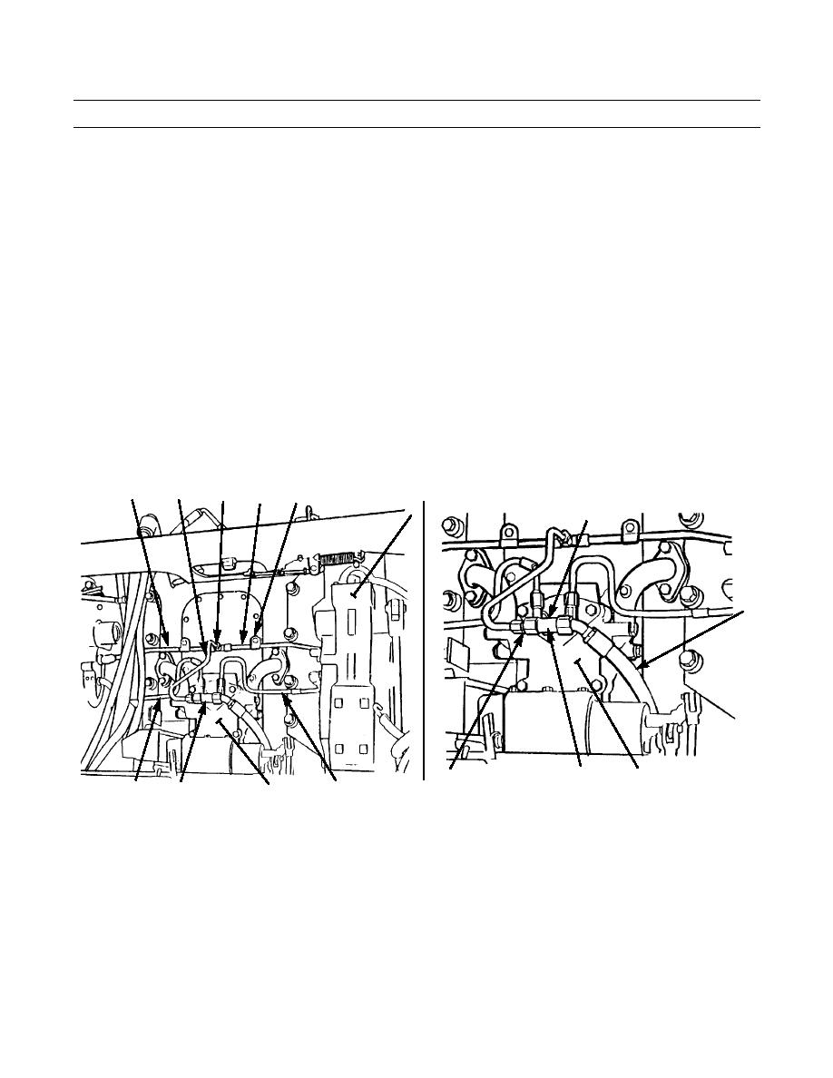
On tractors equipped with ripper, move ripper hydraulic lines away from brake fluid lines connecting two
brake control housings.
15.
Remove two capscrews (24), spacers (25) and clips (26) holding tube assemblies (27 and 28) on frame.
16.
Disconnect and remove tube assembly (29) from tees (30 and 31).
17.
Disconnect and remove tube assembly (27) between hydraulic control (12) and tee (31).
18.
Repeat step 17 for tube assembly (28) from other hydraulic control and tee (31).
19.
Disconnect and remove tube assembly (32) between hydraulic control (12) and elbow on top of steering clutch control
valve (33).
20.
Repeat step 19 for tube assembly (34) from other hydraulic control to steering clutch control valve (33).
21.
Remove nut (35) and adapter (36) from one side of tee (30) on steering clutch control valve (33).
22.
Remove hose assembly (37) from other side of tee (30).
23.
Remove tee (30) and adapter (38) from top of steering clutch control valve (33).
24.
Remove O-ring (39) from adapter (38). Discard O-ring.
29
31
28
27 24,25,26
12
30
37
387-708
35,36
38,39
33
387-707
33
32
34
30
0151 00-4
|
|
Privacy Statement - Press Release - Copyright Information. - Contact Us |
