 |
|||
|
|
|||
|
|
|||
| ||||||||||
|
|
 TM 5-2410-237-23
STEERING BRAKE ACTUATING MECHANISM MAINTENANCE - CONTINUED
0150 00
ASSEMBLY - CONTINUED
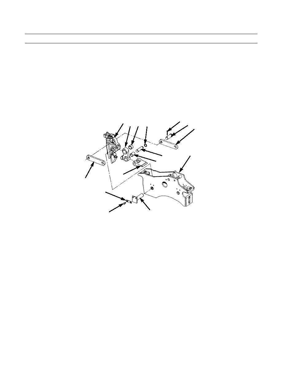
6.
Install two links (22) on lever (49) with pin (48) and new cotter pin (47).
7.
Install smaller bearing (45) and larger bearing (46) in lever (44).
8.
Install strut (3) on lever (44) with pin (43) and retaining ring (42). If removed install other retaining ring on pin.
9.
Position lever (49) with assembled components in actuating mechanism (2). Line up holes and partially insert shaft (41)
into one side of lever.
10.
Position lever (44) with strut (3) in lever (49). Line up holes and insert shaft (41) through both levers (44 and 49) and
actuating mechanism (2).
11.
Install lock (29) and two capscrews (40) to secure shaft (41). Bend lock.
47
49 44
48
46 42
22
2
43
45
3
22
29
387-698
41
40
12.
Install bearings (37, 38 and 39) in lever (32).
13.
Install strut (3) on lever (32) with pin (36) and retaining ring (35). If removed, install other retaining ring in pin.
14.
Install two links (21) on other end of lever (32) with pin (34) and retaining ring (33). If removed, install other retaining
ring in pin.
15.
Position lever (32) and strut (3) in actuating mechanism (2). Line up holes and insert shaft (31) through actuating mech-
anism and lever.
16.
Install lock (29) and two capscrews (30) to secure shaft (31). Bend lock.
0150 00-8
|
|
Privacy Statement - Press Release - Copyright Information. - Contact Us |
