 |
|||
|
|
|||
|
|
|||
| ||||||||||
|
|
 TM 5-2410-237-23
STEERING CLUTCH LEVERS AND LINKAGE MAINTENANCE - CONTINUED
0148 00
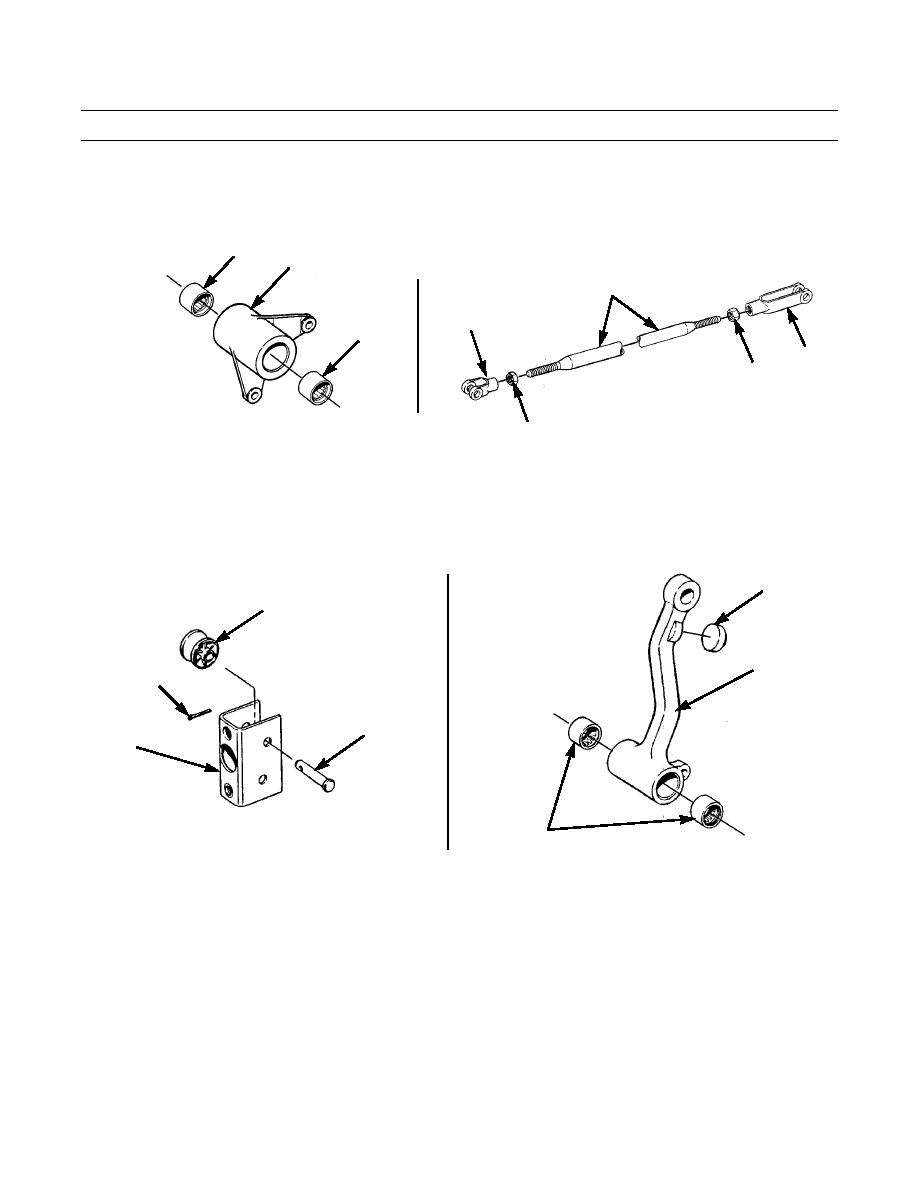
DISASSEMBLY - CONTINUED
5.
Remove two bearings (47) from bellcrank (19).
6.
Loosen two nuts (48) on rod (22) and remove rod ends (49 and 50) and nuts.
47
19
22
50
47
49
48
387-405
387-404
48
ASSEMBLY
1.
Install roller (42) and pin (41) in bracket (14) and install new cotter pin (40) in pin.
2.
Repeat step 1 for other roller (42) in other bracket (14).
3.
Install two bearings (44) and bumper (43) in lever (18).
43
42
18
40
41
14
387-401
44
387-402
387 402
4.
Install two nuts (45) and rod ends (46) on rod (17). Adjust rod ends to 18.50 in. +/- 0.02 in. (46.99 cm +/- 0.05 cm)
between center lines of holes in rod ends.
5.
Tighten two nuts (45) against rod ends (46).
6.
Install two bearings (47) in bellcrank (19).
7.
Install two nuts (48) and rod ends (49 and 50) on rod (22). Do not tighten nuts at this time.
INSTALLATION
1.
Pull shaft (39) out far enough to install clutch linkage bellcrank (19) on shaft (39) and reinsert shaft into support bracket.
2.
Install lock (38) with capscrew (36) and new lockwasher (37) to secure shaft (39).
0148 00-5
|
|
Privacy Statement - Press Release - Copyright Information. - Contact Us |
