 |
|||
|
|
|||
|
|
|||
| ||||||||||
|
|
 TM 5-2410-237-23
STEERING BRAKE PEDALS AND LINKAGE MAINTENANCE - CONTINUED
0146 00
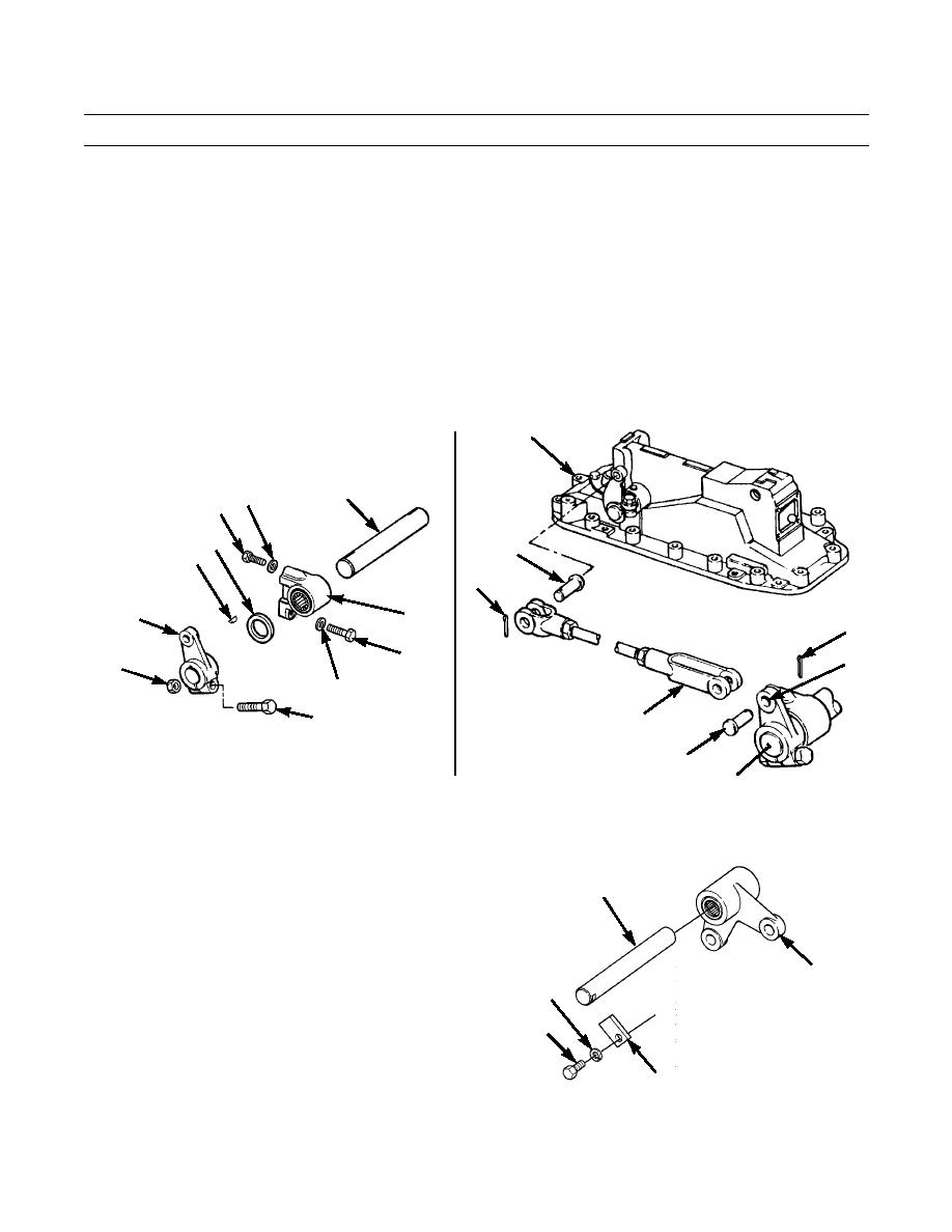
INSTALLATION
1.
Install two brackets (29) on shaft (9).
2.
Install washer (33), new key (34) and lever (30) on end of shaft (9).
3.
Install capscrew (32) and nut (31) in lever (30) to secure lever to shaft (9).
4.
Repeat steps 2 and 3 for lever (30) at other end of shaft (9).
5.
Install two brackets (29) with shaft (9) and levers (30) on crossbeam in floor using four capscrews (27) and new lock-
washers (28).
6.
Install one end of rod assembly (25) on brake actuating mechanism (26) with pin (24) and new cotter pin (23). Do NOT
tighten rod assembly nut at this time.
7.
Repeat step 6 for other end of rod assembly (25) on lever (30) at end of shaft (9). Do NOT tighten rod assembly nut at
this time.
26
9
27 28
33
24
34
23
29
30
23
27
30
31
28
32
25
387-338
24
387-337
9
8.
Remove shaft (22) from steering clutch bellcrank. Position brake bellcrank (10) and reinsert shaft through both
bellcranks and support bracket.
9.
Install lock (21) on bellcrank support bracket with
22
capscrew (19) and new lockwasher (20).
10
20
19
21
387-336
0146 00-5
|
|
Privacy Statement - Press Release - Copyright Information. - Contact Us |
