 |
|||
|
|
|||
|
Page Title:
STEERING BRAKE PEDALS AND LINKAGE ADJUSTMENT |
|
||
| ||||||||||
|
|
 TM 5-2410-237-23
STEERING BRAKE PEDALS AND LINKAGE ADJUSTMENT
THIS WORK PACKAGE COVERS
Adjustment
INITIAL SETUP
Tools and Special Tools
Materials/Parts - Continued
Gasket (4)
Tool kit, general mechanic's (Item 122, WP 0250
Pin, cotter (8)
Shop equipment, common no. 1 (Item 103, WP
Equipment Condition
Battery disconnect switch in OFF position (TM 5-
Materials/Parts
2410-237-10)
Rag, wiping (Item 29, WP 0249 00)
Floor plates removed (WP 0171 00)
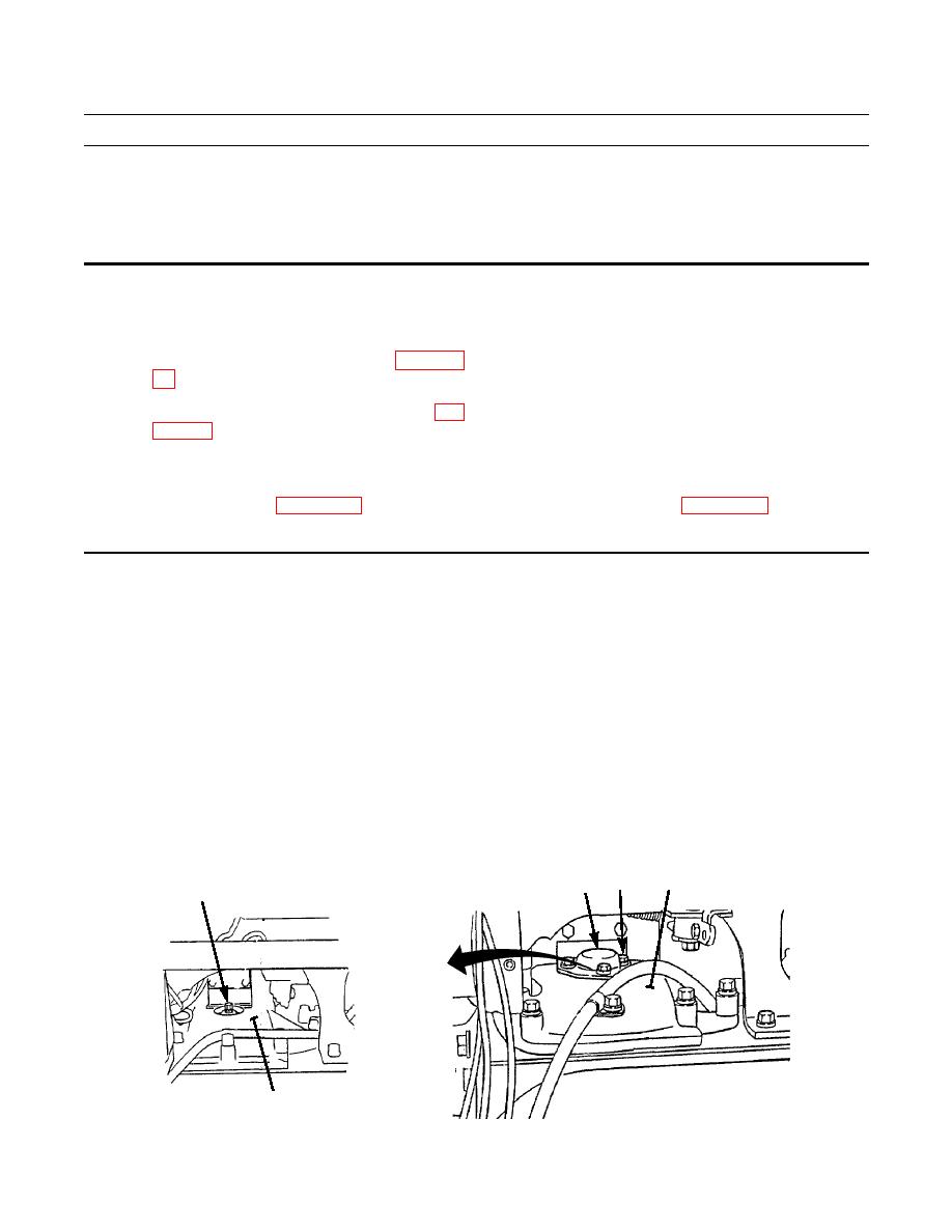
ADJUSTMENT
NOTE
The following procedure is for R.H. linkage. Repeat procedure for L.H. linkage.
1.
Remove three capscrews (1) and washers (2) from cover (3).
2.
Remove cover (3) and gasket (4) from top of final drive case (5) to gain access to brake band adjusting screw (6). Dis-
card gasket.
3.
Turn brake band adjusting screw (6) clockwise until band is tight, then loosen 1-1/2 turns (9 clicks) counterclockwise.
1,2
5
3,4
6
5
387-355
|
|
Privacy Statement - Press Release - Copyright Information. - Contact Us |
