 |
|||
|
|
|||
|
|
|||
| ||||||||||
|
|
 TM 5-2410-237-23
STEERING AND BRAKE SYSTEM THEORY OF OPERATION - CONTINUED
0144 00
BRAKES - CONTINUED
3.
When the brake pedal is released, spring (22) and
10 22 23
springs inside the hydraulic control mechanism move
9
8
11
the mechanical linkage and brake pedal. The struts
move away from each other. The brake band is not in
12
contact with the steering clutch drum. Now, the brakes
17
are in the "OFF" position.
14
4.
Both brakes can be held in the "ON" position. Push
16
both brake pedals toward the front of the machine. At
15
the same time, push the parking brake lever forward
and down. The parking brake lever is at the right side
of the seat. The movement of the pawl (8) moves rod
(23) and engages the teeth of the pawl (8) with the
19
teeth of the ratchet. The brakes are held in the "ON"
position by the link. The links push against the
bellcrank (10). To release the brakes, push on the
21
brake pedals and pull the parking brake lever up and
13
18
backwards.
5.
An oil line sends pressure oil to each brake band. This
oil is for lubrication and cooling of the brake bands.
20
387-533
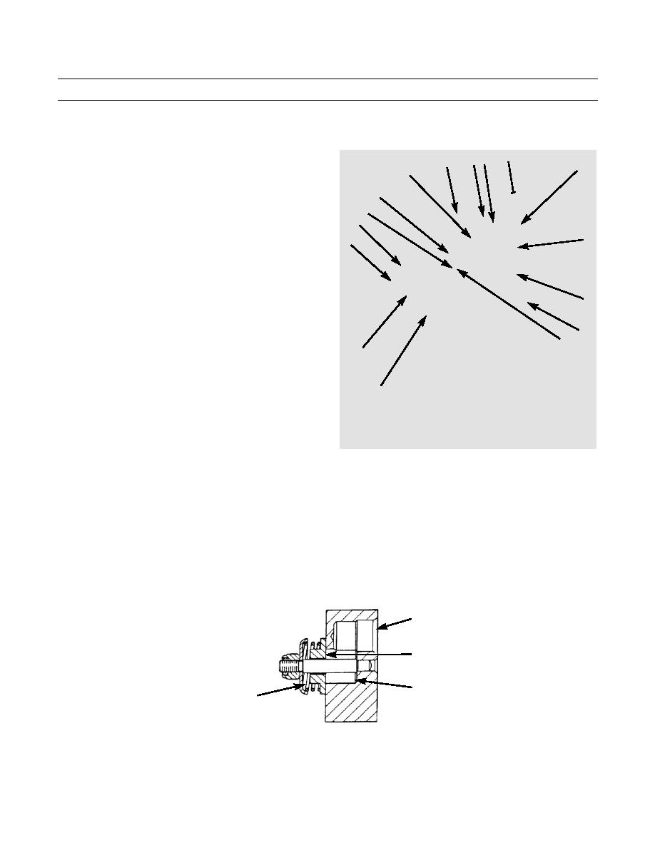
RELIEF VALVE FOR BRAKE COOLING AND LUBRICATION
The relief valve for brake cooling and lubrication is in the compartment for the left steering clutch. It lets oil at a specific
pressure go to the brake bands. Cool oil goes in the valve through opening (24) and fills chamber (25). The oil comes from the
oil cooler and goes through the lubrication manifold on the transmission case. Chamber (25) has two openings. A hose is con-
nected to each of the openings. One hose goes to the right brake band and the other hose goes to the left brake band. The oil
goes from chamber (25) through the two hoses to the brake bands. The oil pressure to the brake bands is controlled by spring
(26) and valve (27). When the pressure of the oil in chamber (25) goes above 50 psi +/- 5 psi (345 kPa +/- 34 kPa), valve (27)
moves and lets the extra oil go to the compartment for the left steering clutch.
24
27
25
26
387-534
END OF WORK PACKAGE
0144 00-2
|
|
Privacy Statement - Press Release - Copyright Information. - Contact Us |
