 |
|||
|
|
|||
|
Page Title:
STEERING AND BRAKE SYSTEM THEORY OF OPERATION |
|
||
| ||||||||||
|
|
 TM 5-2410-237-23
STEERING AND BRAKE SYSTEM THEORY OF OPERATION
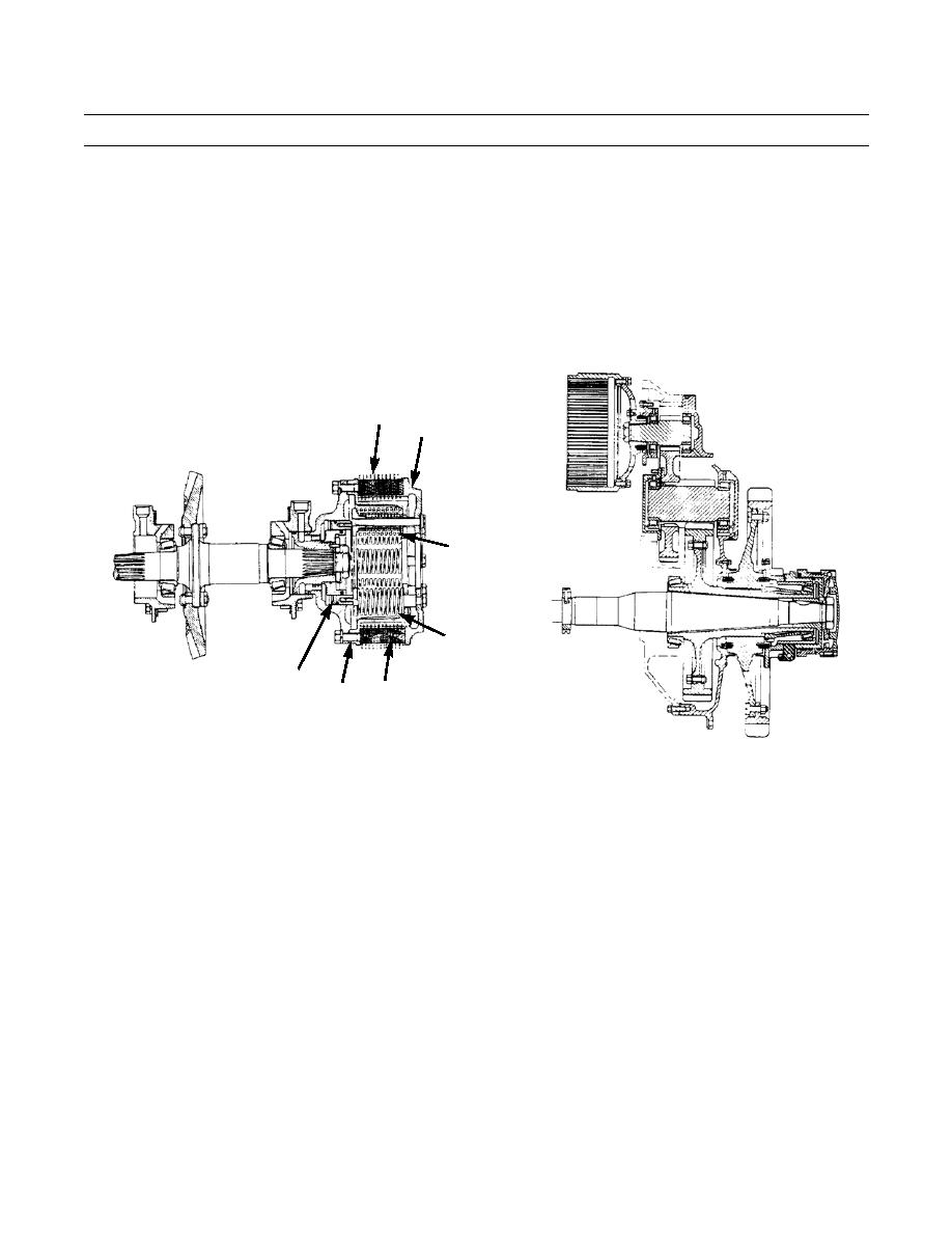
STEERING CLUTCH
1.
With a steering clutch engaged, the force of springs (1 and 2) keeps pressure plate (3), steel discs (4) and disc assemblies
(5) against inner drum (6). Power goes from the inner drum, through the discs, to the outer drum (brake drum). The
steering clutches are normally engaged.
2.
With a steering clutch released, pressure oil from the hydraulic controls for the steering clutches moves piston (7)
toward the outside of the machine. The piston pushes on the spring retainer. The spring retainer pushes on springs (1 and
2) and puts them in compression. At the same time, the spring retainer pushes pressure plate (3) toward the outside of
the machine. The pressure plate is now not in contact with steel discs (4) and disc assemblies (5). The disc and disc
assemblies are not held together. Power cannot go from the inner drum to the outer drum.
5
3
1
2
7
4
6
387-510
HYDRAULIC CONTROL VALVE FOR STEERING CLUTCHES
Pressure oil is sent to the hydraulic control valve by the transmission oil pump. When the control levers are pulled,
levers move plungers to the left. The plungers move spring-tensioned valve spools. The movement of the valve spools lets oil
go to the steering clutch pistons. The oil pushes against the pistons. The pistons push against the springs and move the pressure
plates away from the disc assemblies which releases the steering clutches.
BRAKES
1.
Two band-type brakes, one on each steering clutch drum, stop the movement of the machine. The brakes also give assis-
tance to the steering clutches to turn the machine. The operation of each brake gets assistance from a hydraulic control
mechanism. The operation of each brake is separate from the other. Both brakes can be held in the "ON" position by
pawl (8) on the brake linkage.
2.
The operation of both brakes is the same. When a brake pedal is pushed toward the front of the machine, mechanical
linkage moves piston (9) in the hydraulic control mechanism. The piston pushes against the roller on bellcrank (10). The
bellcrank turns on the shaft (11) and moves the link (12) toward the top. This moves pin (13) toward the top and pins (14
and 15) away from each other. Levers (16 and 17) then turn on shafts (18 and 19). Levers (16 and 17) move struts (20
and 21) toward each other. As the struts move toward each other, they push on the ends of the brake band. This causes
the brake to make contact with the brake drum, stopping or slowing the machine.
|
|
Privacy Statement - Press Release - Copyright Information. - Contact Us |
