 |
|||
|
|
|||
|
|
|||
| ||||||||||
|
|
 TM 5-2410-237-23
DRIVE SPROCKET SHAFT REPLACEMENT - CONTINUED
0142 00
REMOVAL - CONTINUED
3.
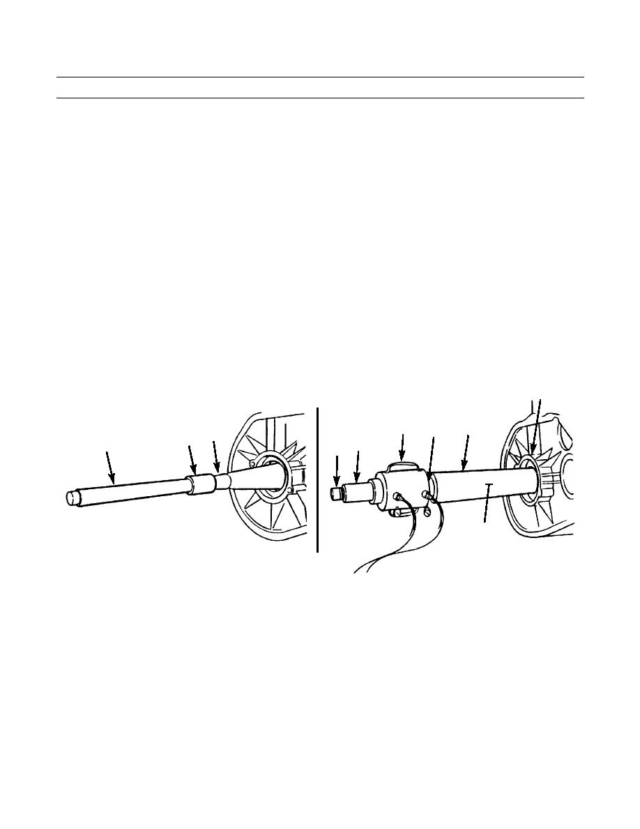
Install threaded adapter (4) on sprocket shaft (5) and turn until all threads are engaged.
4.
Install and turn stud extension (6) completely into adapter (4).
NOTE
When installing protective sleeve (7), ensure slot opening is away from bevel gear case.
5.
Install protective sleeve (7) over stud extension (6) until sleeve contacts bevel gear case (8).
6.
Install head (9) into protective sleeve (7).
7.
Install cylinder (10) on stud extension (6) and against head (9) and secure with nut (11).
8.
Connect hydraulic pump to cylinder (10) and hold protective sleeve (7) and head (9) in alignment.
9.
Apply pressure to sprocket shaft (5) to loosen from taper.
WARNING
Ensure piston of cylinder (10) is retracted and pressure is off prior to removal of tools. Failure to follow this
warning could result in personal injury.
10.
Remove tooling from sprocket shaft (5).
8
7
10
9
5
4
11
6
6
5
(HIDDEN)
387-611
387-612
0142 00-2
|
|
Privacy Statement - Press Release - Copyright Information. - Contact Us |
