 |
|||
|
|
|||
|
|
|||
| ||||||||||
|
|
 TM 5-2410-237-23
TRACK IDLER REPLACEMENT - CONTINUED
0138 00
INSTALLATION
WARNING
Use extreme caution when handling heavy parts. Provide adequate support and use assistance during pro-
cedure. Ensure that any lifting device used is in good condition and of suitable load capacity. Keep clear of
heavy parts supported only by lifting device. Failure to follow this warning may result in death or injury to
personnel.
NOTE
Idler weighs 500 lb (227 kg).
Apply antiseize compound to all capscrews before installation.
1.
Attach a suitable lifting device to both sides of idler (5). Lift idler into position on track roller frame (20).
2.
Install two new lockwashers (13) and capscrews (12) through bearing (14) into yoke (15) on each side of idler (5).
NOTE
Minimum clearance must be 0.030-0.075 in. (0.76-1.91 mm) between yoke (15) and plate assembly (21). Add
or remove shim(s) (18) as necessary.
3.
Install shims (18), three new lockwashers (17) and capscrews (16) at top of collar (19) and bearing (14) on each side of
idler (5).
4.
Install plate (11), two spacers (8), four new lockwashers (7), capscrews (6) and two strips (10) to both sides of idler (5).
Leave capscrews loose for shimming.
NOTE
Add or remove shims (9) as needed to provide a clearance of 0.030 in. +/- 0.020 in. (0.76 mm +/- 0.51 mm)
between plate (11) and track roller frame (20).
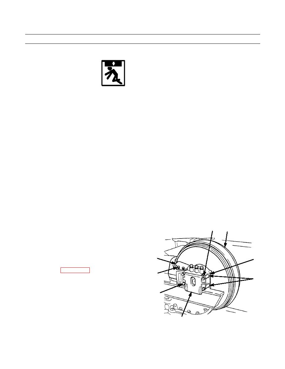
5.
Remove two capscrews (6) and lockwashers (7) and
9
5
install shims (9) between plate (11) and spacers (8) on
each side of idler (5).
6.
Reinstall capscrews (6) and lockwashers (7). Tighten
capscrews to 200 lb-ft (271 Nm).
7.
Install guard (4) with two capscrews (1), new lock-
4
10
washers (3) and washers (2) on each side of idler (5).
8.
Connect track (WP 0143 00).
1,2,3
9.
Test drive and check track for proper operation (TM 5-
8
2410-237-10).
6,7
11
387-605
END OF WORK PACKAGE
0138 00-3
|
|
Privacy Statement - Press Release - Copyright Information. - Contact Us |
