 |
|||
|
|
|||
|
|
|||
| ||||||||||
|
|
 TM 5-2410-237-23
TRACK ROLLER FRAME ASSEMBLY REPLACEMENT - CONTINUED
0135 00
INSTALLATION - CONTINUED
8.
Install pads (9) and plate (8) in position on track roller frame (1).
WARNING
Use extreme caution when handling heavy parts. Provide adequate support and use assistance during
procedure. Ensure that nay lifting device used is in good condition and of suitable load capacity. Keep
clear of heavy parts supported only by lifting device. Failure to follow this warning may result in death
or injury to personnel.
NOTE
Weight of front support assembly is approximately 70 lb (32 kg).
9.
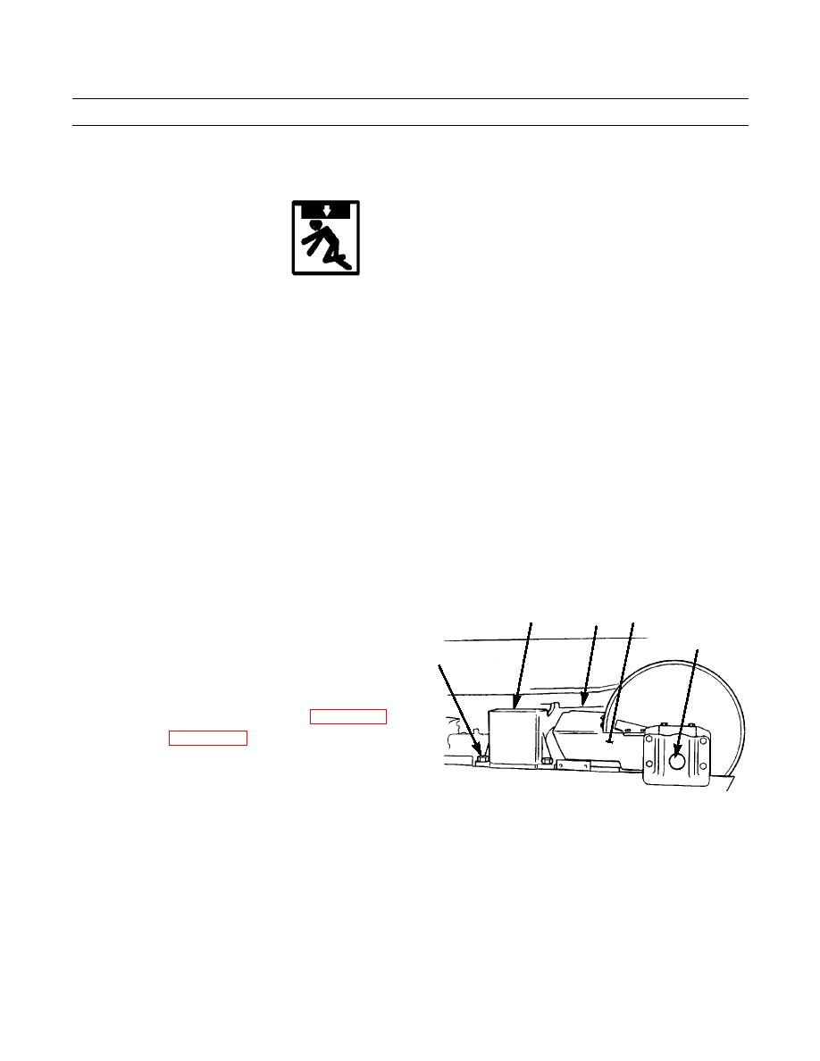
Attach lifting device to lifting links (2) and to front support assembly (3) and point (4) on front of track roller frame (1).
10.
Attach ratchet puller to front of track roller frame (1) and point (4).
NOTE
Do not hit front support assembly (3) when track roller frame is put into position under equalizer bar (5).
11.
Lift track roller frame (1) into position on equalizer bar (5).
12.
Lift track roller frame (1) and use ratchet puller to raise evenly until capscrew holes in front support assembly (3) are
aligned with capscrew holes in track roller frame.
13.
Install front support assembly (3) to track roller frame
1
2,3
5
(1) with four new lockwashers (7) and capscrews (6).
4
Tighten capscrews to 350 lb-ft (475 Nm).
6,7
14.
Lower track roller frame (1) until weight is on equal-
izer bar (5). Remove lifting device, bolts, lifting links
and ratchet puller.
15.
Install track roller frame guard covers (WP 0163 00).
16.
Install track (WP 0143 00).
387-684
ALIGNMENT
1.
Place machine on flat and level surface.
2.
Measure and mark centerline of sprocket (18) and centerline of rear track carrier roller (10). Centerlines should be lined
up with each other. Distance A should equal distance B.
3.
If centerline of sprocket (18) is more than 0.06 in. (1.5 mm) from centerline of rear track carrier roller (10), perform
steps 4-12 to align track roller frame.
0135 00-5
|
|
Privacy Statement - Press Release - Copyright Information. - Contact Us |
