 |
|||
|
|
|||
|
Page Title:
RECOIL SPRINGS AND TRACK ADJUSTER |
|
||
| ||||||||||
|
|
 TM 5-2410-237-23
TRACK THEORY OF OPERATION - CONTINUED
0130 00
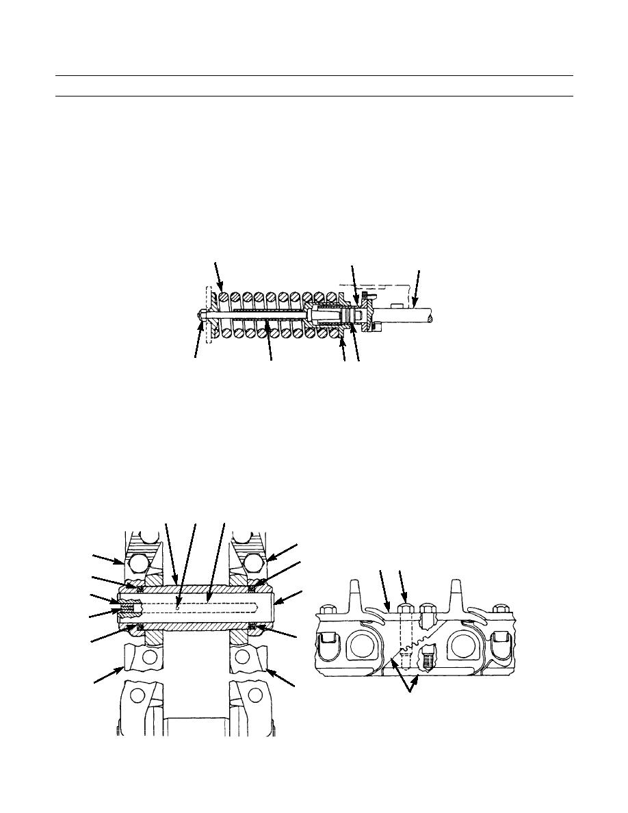
RECOIL SPRINGS AND TRACK ADJUSTER - CONTINUED
2.
Track adjustment is made by adding to cavity (1) through a fill valve. This moves recoil rod (2) and the front idler
toward the front of the machine. The movement of the recoil rod and front idler tightens the track. The tension on the
track is released by a relief valve.
3.
If rocks or debris get between the track and the rollers, idler or sprocket, recoil rod (2) moves toward the rear of the
machine. The movement of the recoil rod tightens the track. Since the grease in cavity (1) cannot be compressed, piston
(3) and bolt (4) move toward the rear of the machine. Bolt (4) pushes pilot (5) toward the rear of the machine. Pilot (5)
pushes on spring (6). This puts spring (6) in compression. The movement of pilot (5) and the compression of spring (6)
prevent too much tension on the track.
4.
Nut (7) is used to keep recoil spring in compression when it is installed in the machine.
6
1
2
387-319
7
4
5 3
TRACK
1.
The machine has sealed and lubricated track. Each track assembly has links, pins, bushings, thrust rings, polyurethane
seal assemblies, rubber stoppers and polyurethane plugs.
2.
Each of the track links (8 and 9) makes a fit over the track links in front of them. Link (8) makes a fit over link (10). Link
(9) makes a fit over link (11). The connection of the track links makes the track assembly.
3.
Each link has a counterbore in the end which makes a fit with the link in front of it. Seal assemblies (12 and 13) are
installed in the counterbores of the links. Each seal assembly has a load ring and a seal ring. The load ring pushes the
seal ring against the end of bushing (14) and the link counterbore.
18
19
14
9
8
13
23 24
12
17
20
21
16
15
10
11
22
387-320
0130 00-2
|
|
Privacy Statement - Press Release - Copyright Information. - Contact Us |
