 |
|||
|
|
|||
|
|
|||
| ||||||||||
|
|
 TM 5-2410-237-23
FINAL DRIVE PINIONS AND FLANGES MAINTENANCE - CONTINUED
0126 00
INSTALLATION
1.
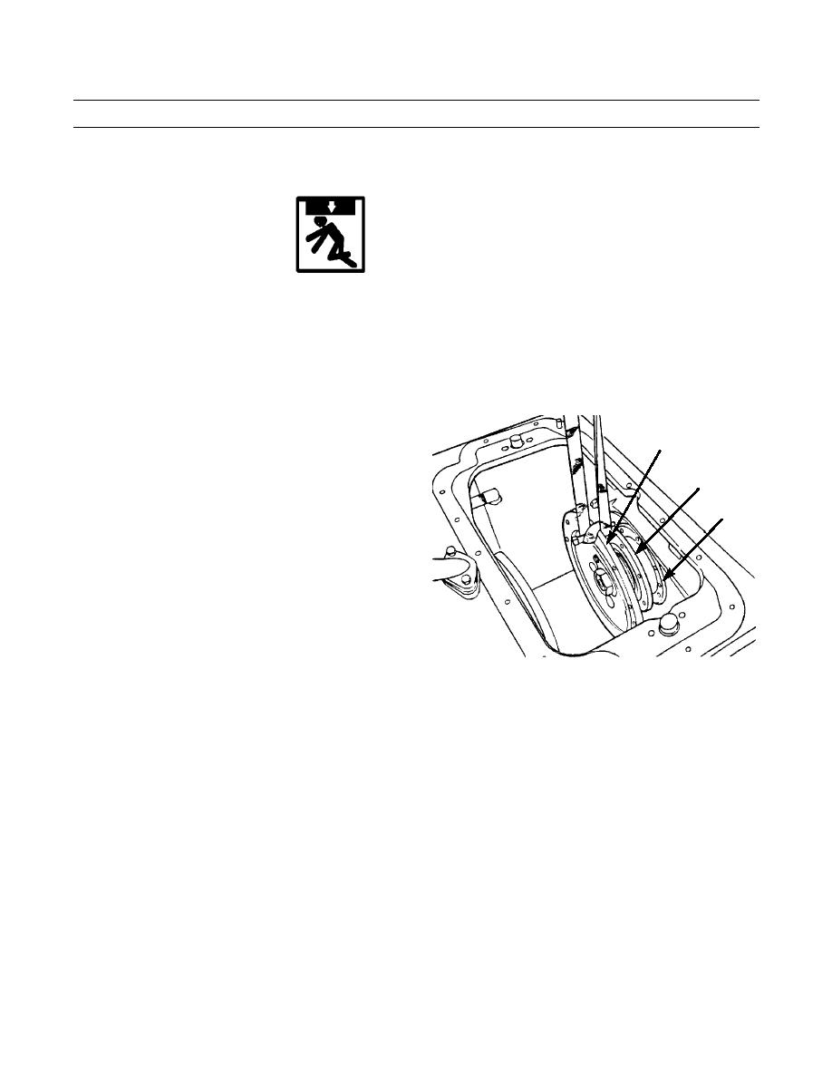
Apply silicone gasket forming compound on flange of bearing cage (4) and cage mounting surface on bevel gear case.
WARNING
Use extreme caution when handling heavy parts. Provide adequate support and use assistance during pro-
cedure. Ensure that any lifting device used is in good condition and of suitable load capacity. Keep clear of
heavy parts supported only by lifting device. Failure to follow this warning may result in injury to person-
nel.
NOTE
Weight of final drive pinion (6) and flange (1) as a unit is 80 lb (36 kg).
2.
Use a nylon sling and a suitable lifting device to install
final drive pinion (6) and flange (1) as a unit on bevel
1
gear case. Ensure unit is positioned as follows:
a.
Engage unit with teeth on final drive gear inside
4
bevel gear case.
b.
Seat final drive pinion bearing race (14) in bear-
6
ing inside bevel gear case.
c.
Position bearing cage (4) flange with dowel hole
up, oil hole down and capscrew holes aligned
with holes in bevel gear case.
3.
Attach lifting equipment to track and move track to
align holes in flange (1) with holes in bearing cage (4).
387-778
NOTE
Flange may have to be rotated slightly to gain access to some capscrews.
4.
Install seven washers (5) and capscrews (3) to secure bearing cage (4). Tighten capscrews to 100 lb-ft (140 Nm).
NOTE
If final drive pinion and flange were NOT disassembled, skip step 5.
0126 00-7
|
|
Privacy Statement - Press Release - Copyright Information. - Contact Us |
