 |
|||
|
|
|||
|
|
|||
| ||||||||||
|
|
 TM 5-2410-237-23
0125 00
REMOVAL
NOTE
This procedure applies to either R.H. or L.H. final drive assembly.
1.
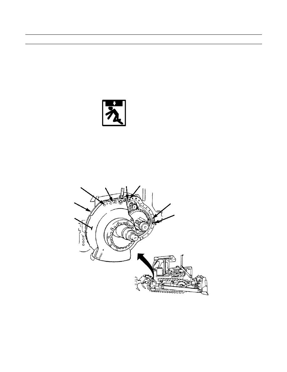
Remove two capscrews (1) and washers (2) from final drive case (3).
WARNING
Guide pins must be installed as instructed in step 2 to avoid personal injury.
2.
Install two 5/8 in. -11NC guide pins (4) and three 1/2 in. -13NC forcing screws (5) in final drive case (3).
3.
Remove 29 remaining capscrews (1) and washers (2) from final drive case (3).
4.
Tighten forcing screws (5) evenly until final drive case (3) is approximately 0.25 in. (6.3 mm) away from steering clutch
case (6).
5
4
1,2
5
5
6
4
3
387-281
CAUTION
Use a piece of wire to keep idler pinion in position so it will not fall from steering clutch case when final
drive case is removed.
5.
Install a piece of wire (A) around two guide pins (4) and across face of idler pinion to hold idler pinion in place.
0125 00-2
|
|
Privacy Statement - Press Release - Copyright Information. - Contact Us |
