 |
|||
|
|
|||
|
|
|||
| ||||||||||
|
|
 TM 5-2410-237-23
TRANSMISSION RELIEF VALVE REPLACEMENT - CONTINUED
0119 00
INSTALLATION - CONTINUED
7.
Install hose assembly (10) to relief valve (5) with two flanges (9), four washers (8) and capscrews (7).
8.
Install new O-ring (6) in hose assembly (4). Install hose assembly to relief valve (5) with two flanges (3), four washers
(2) and capscrews (1).
9.
Check transmission oil level and add as needed (WP 0107 00).
10.
As required, check relief valve setting by performing power train hydraulic system tests (WP 0122 00). Perform Relief
Valve Adjustment below as required.
11.
Run engine and test drive in all speeds.
12.
Install floor plates (WP 0171 00).
RELIEF VALVE ADJUSTMENT
NOTE
Adjustment can be performed without removing valve from torque divider.
1.
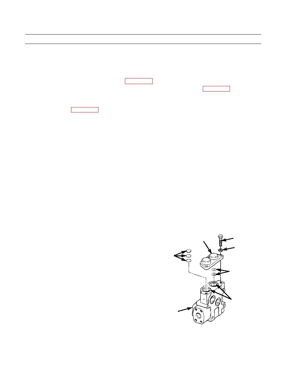
Remove two capscrews (21), lockwashers (22), cover (23) and two O-rings (24) from relief valve (5). Discard O-rings
and lockwashers.
2.
Add spacers (25) to increase relief valve setting or remove spacers to decrease setting:
a. Each 0.010 in. (0.25 mm) spacer will change relief pressure by 4.2 psi (29 kPa).
b. Each 0.036 in. (0.91 mm) spacer will change relief pressure by 15.1 psi (104 kPa).
c. Each 0.062 in. (1.57 mm) spacer will change relief pressure by 26.4 psi (182 kPa).
3.
Add spacers (26) to increase relief valve setting or remove spacers to decrease setting:
a.
Each 0.010 in. (0.25 mm) spacer will change relief pressure by 1.3 psi (9 kPa).
b.
Each 0.036 in. (0.91 mm) spacer will change relief pressure by 4.7 psi (33 kPa).
NOTE
Lightly coat new O-rings with clean oil before installation.
4.
When adjustments are correct, install two new O-rings
21
23
(24), cover (23), two new lockwashers (22) and cap-
screws (21). Tighten capscrews to 18 lb-ft (24 Nm).
22
25
26
24
5
387-842
END OF WORK PACKAGE
0119 00-3
|
|
Privacy Statement - Press Release - Copyright Information. - Contact Us |
