 |
|||
|
|
|||
|
|
|||
| ||||||||||
|
|
 TM 5-2410-237-23
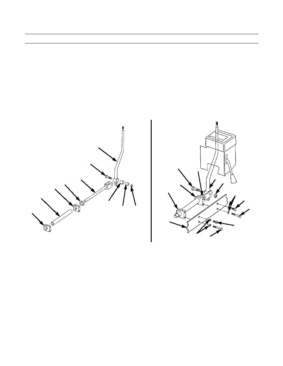
TRANSMISSION SELECTOR LEVER AND LINKAGE MAINTENANCE - CONTINUED
0104 00
REMOVAL - CONTINUED
12.
Remove self-locking nut (39) from capscrew (40). Discard self-locking nut.
13.
Remove two short capscrews (41), two long capscrews (42) and four lockwashers (43) from two clamps (44) and plate
(45). Discard lockwashers.
14.
Move shaft assembly (46) from selector lever (32) and remove capscrew (40) and spacer (47).
15.
Slide support (48) and spacer (49) from shaft (25).
16.
Remove clamps (44) from support (48).
17.
If damaged, press bushing (50) from selector lever (32).
32
40
40
46
32
25
39
44
49
44
44
43
48
41
50
42
39
47
44
45
41
387-521
43
387-520
42
INSTALLATION
1.
If removed, press bushing (50) into selector lever (32).
2.
Position two clamps (44) on support (48).
3.
Install spacer (49) and support (48) on shaft (25).
4.
Hold shaft assembly (46) and selector lever (32) in place and install capscrew (40) and spacer (47).
5.
Hold shaft assembly (46) in position and align holes in clamps (44) with holes in plate (45).
NOTE
Short capscrews must be installed in top holes of clamp and long capscrews in bottom holes of clamp.
6.
Install clamps (44) to plate (45) with four new lockwashers (43), two short capscrews (41) and two long capscrews (42).
7.
Install new self-locking nut (39) on capscrew (40).
0104 00-4
|
|
Privacy Statement - Press Release - Copyright Information. - Contact Us |
