 |
|||
|
|
|||
|
Page Title:
ELECTRICAL SYSTEM THEORY OF OPERATION |
|
||
| ||||||||||
|
|
 TM 5-2410-237-23
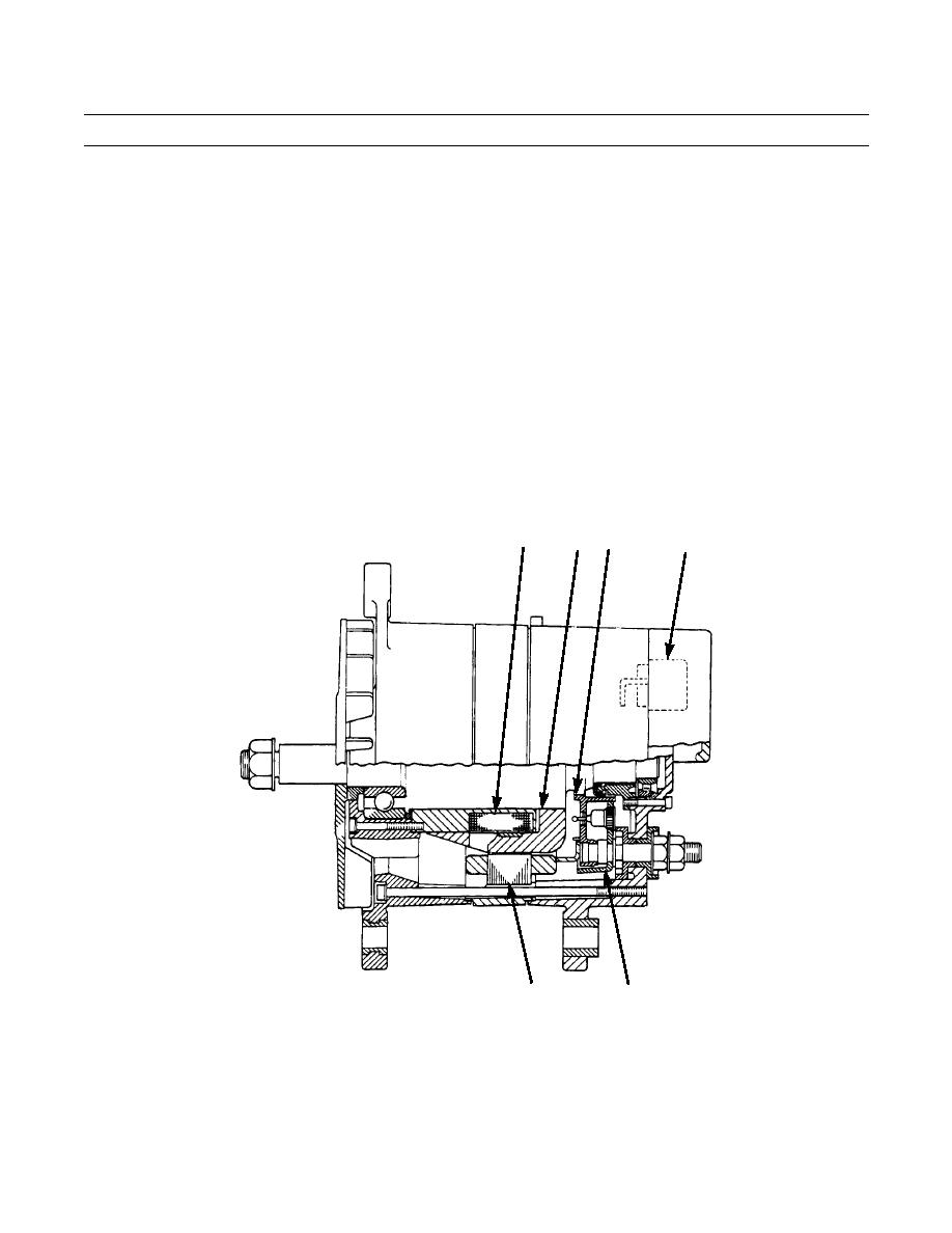
ELECTRICAL SYSTEM THEORY OF OPERATION
ALTERNATOR
1.
The alternator is driven by three V-type belts from the crankshaft pulley. This alternator is a three phase, full-wave recti-
fied output with an integral voltage regulator.
2.
The alternator design has no need for slip rings or brushes, and the only part that has movement is the rotor assembly.
All conductors that carry current are stationary. The alternator has a 50 amp output at 28 VDC.
3.
The rotor assembly (1) has many magnetic poles like fingers with air space between each opposite pole. The poles have
residual magnetism (like permanent magnets) that produce a small amount of magnet-like lines of force (magnetic field)
between the poles. As the rotor assembly begins to turn between the field winding (2) and the stator winding (3), a small
amount of alternating current (AC) is produced in the stator winding (3), from the small magnetic lines of force made by
the residual magnetism of the poles. This AC current is changed to direct current (DC) when it passes through the diodes
(4) of the rectifier bridge (5). Most of this current goes to charge the battery and to supply the low amperage circuit, and
the remainder is sent on to the field windings (2). The DC current flow through the field winding (2) (wires around an
iron core) now increases the strength of the magnetic lines of force. These stronger lines of force increase the amount of
the AC current produced in the stator winding (3). The increased speed of the rotor assembly (1) also increases the cur-
rent and voltage output of the alternator.
4.
The voltage regulator (6) is a solid state (transistor, stationary parts) electronic switch. It feels the voltage in the system
and switches on and off many times a second to control the field current (DC current to the field windings) for the alter-
nator to make the needed voltage output.
2
1
5
6
387-321
3
4
|
|
Privacy Statement - Press Release - Copyright Information. - Contact Us |
