 |
|||
|
|
|||
|
|
|||
| ||||||||||
|
|
 TM 5-2410-237-23
ENGINE ASSEMBLY REPLACEMENT - CONTINUED
0021 00
REMOVAL - CONTINUED
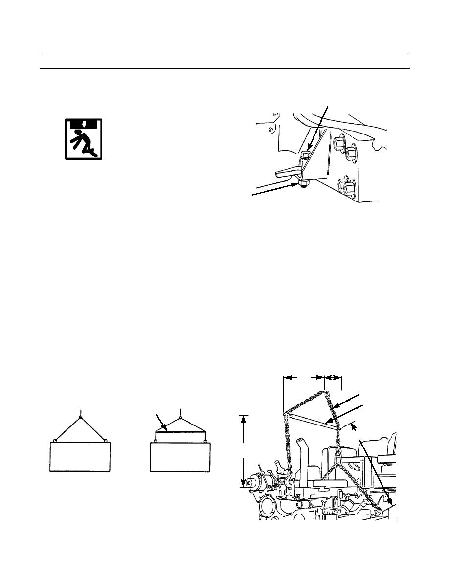
23.
Remove two capscrews (58), nuts (59) and washers
58
(60) from engine front support.
WARNING
Use extreme caution when handling heavy
parts. Provide adequate support and use
assistance during procedure. Ensure that
any lifting device used is in good condition
59,60
and of suitable load capacity. Keep clear
387-084
of heavy parts supported only by lifting
device. Failure to follow this warning may
result in death or injury to personnel.
CAUTION
Always use a loader leveler while lifting engine assembly. This will keep lifting force vertical at all
times, avoiding damage to lifting brackets.
Engine assembly must be lifted so that crankshaft centerline is horizontal. This will prevent binding on
rear engine mounts locating pins.
NOTE
Weight of engine and torque divider is approximately 3,000 lb (1,362 kg).
24.
Attach load leveler and lifting device (61) to engine lifting brackets according to approximate dimensions shown in
illustration. Lift engine from machine.
25.
Lower engine to a suitable repair stand.
27 IN.
(69 CM)
16 IN.
(41 CM)
61
CORRECT
INCORRECT
LOAD
METHOD
METHOD
LOAD LEVELER
LEVELER
43 IN.
(109 CM)
23 IN.
(58 CM)
ENGINE
ENGINE
387-085
387-086
0021 00-7
Change 1
|
|
Privacy Statement - Press Release - Copyright Information. - Contact Us |
