 |
|||
|
|
|||
|
|
|||
| ||||||||||
|
|
 TM 5-2410-237-23
VALVE MECHANISM MAINTENANCE - CONTINUED
0019 00
ASSEMBLY - CONTINUED
NOTE
During assembly, pay close attention and refer to order of assembly. Ensure exhaust and intake rocker
arms, springs, washers and brackets are installed in correct sequence on rocker shaft.
4.
Install six exhaust rocker arms (22), five intake rocker arms (16), angle brackets (6), twelve washers (21) and five
springs (20) on rocker shaft (5).
5.
Align hole in bracket (7) with hole in rocker shaft (8). Install dowel pin (19) into bracket and shaft. Pin must extend
0.378 in. (9.6 mm) above bracket.
6.
Apply clean lubricating oil on all rocker shaft components after assembly.
INSTALLATION
1.
Install 12 push rods (10) through cylinder head (9) and into block assembly (11).
NOTE
Each time a capscrew is removed from rear support bracket, a new O-ring must be installed.
Apply clean lubricating oil to new O-ring prior to installation.
2.
Install new O-ring (12) in rear support bracket (5).
3.
Place rocker shaft (8) into position on cylinder head (9).
CAUTION
Dowel pins on each end of rocker shaft and rocker arm must be in alignment with holes in cylinder head. If
pins and holes are not properly aligned when rocker shaft capscrews are installed and tightened, damage to
rocker shaft could occur.
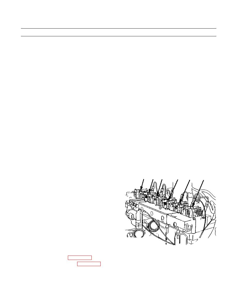
4.
Put antiseize compound on threads of capscrews (3)
E
D
A
B
C
F
and install six washers (4) and capscrews to bracket
(5, 6 and 7), to secure rocker shaft (8) to cylinder head
(9).
5.
Refer to illustration and tighten capscrews (3) as fol-
lows:
a.
Tighten capscrews, in letter sequence, to 115 lb-
ft (156 Nm).
b.
Tighten capscrews, in letter sequence, to 185 lb-
ft (251 Nm).
c.
Tighten capscrews again in letter sequence, to
185 lb-ft (251 Nm).
387-159
6.
If new rocker arms (16 or 22) were installed, install 12 new adjustment screws (2) and nuts (1).
7.
Adjust valve mechanism (WP 0018 00).
8.
Install valve mechanism cover (WP 0017 00).
END OF WORK PACKAGE
0019 00-5
|
|
Privacy Statement - Press Release - Copyright Information. - Contact Us |
