 |
|||
|
|
|||
|
|
|||
| ||||||||||
|
|
 TM 5-2410-237-23
VALVE MECHANISM ADJUSTMENT
THIS WORK PACKAGE COVERS
Locating Top Dead Center (TDC) Compression Stroke for Number 1 Piston, Adjusting Valve Clearance
INITIAL SETUP:
Equipment Condition
Tools and Special Tools
Valve mechanism cover removed (WP 0017 00)
Tool kit, general mechanic's (Item 122, WP 0250
Crankcase guard removed (WP 0157 00)
Shop equipment, common no. 1 (Item 103, WP
Bolt, timing, 3/8 in. -16NC, 2 in. long
LOCATING TOP DEAD CENTER (TDC) COMPRESSION STROKE FOR NUMBER 1 PISTON
NOTE
Engine is seen from vibration damper end when direction of crankshaft rotation is given.
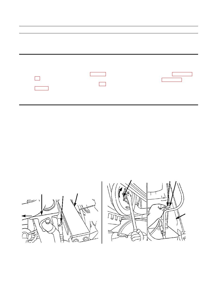
1.
Remove plug (1) from flywheel housing.
NOTE
Perform the following step to remove play from timing gears when engine is set at TDC.
2.
Place socket and breaker bar on mounting capscrew (2) of vibration damper. Turn vibration damper so that flywheel
turns to the right. Turn flywheel until 3/8 in. -16NC bolt (3) can be installed through hole (4) of flywheel housing.
2
3 4
FLYWHEEL
TRANSMISSION
HOUSING
OIL COOLER
1
FLYWHEEL
FRONT OF
HOUSING
TRACTOR
FRONT OF TRACTOR
LEFT SIDE
387-122
387-121
|
|
Privacy Statement - Press Release - Copyright Information. - Contact Us |
