 |
|||
|
|
|||
|
|
|||
| ||||||||||
|
|
 TM 5-2410-237-23
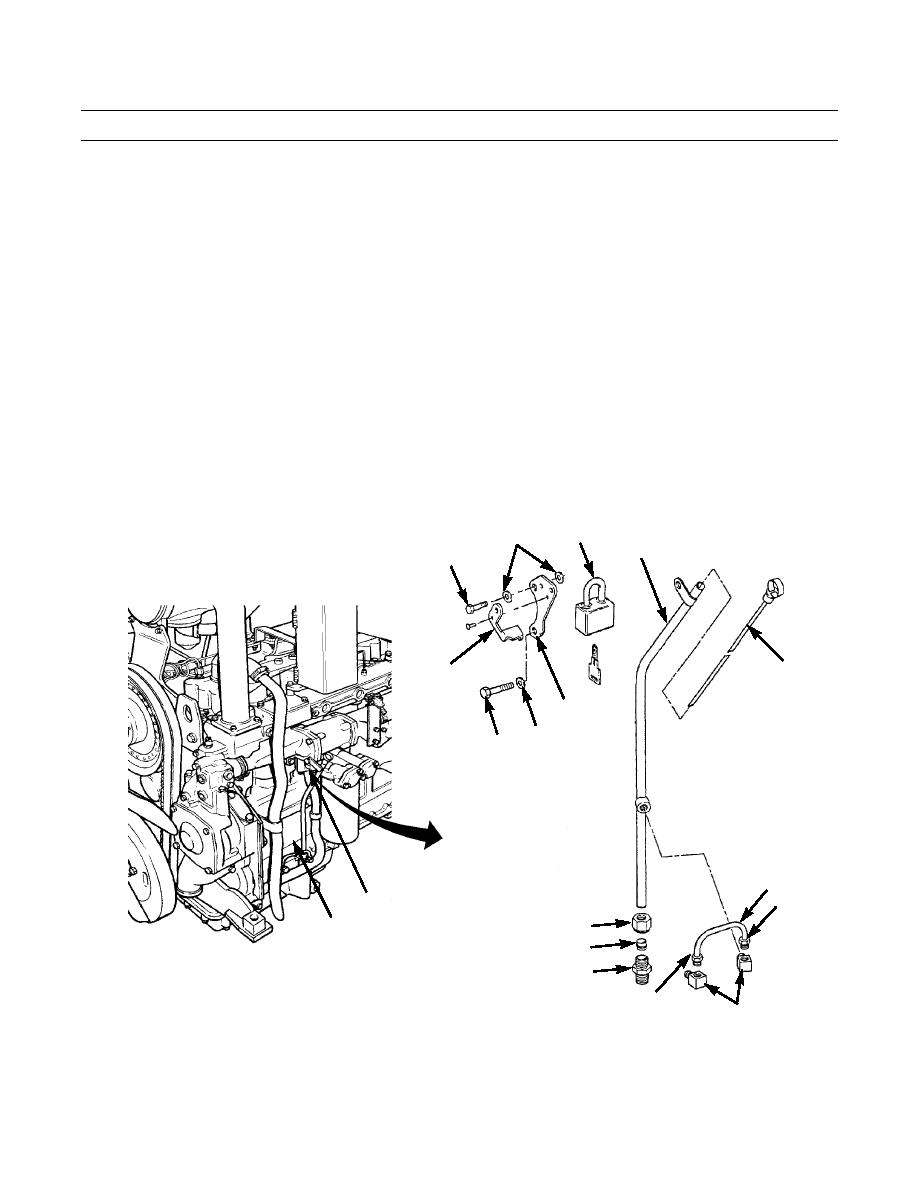
OIL LEVEL GAGE AND GAGE TUBE ASSEMBLY REPLACEMENT - CONTINUED
0012 00
INSTALLATION
1.
Install elbow (10) in engine block (15).
2.
Install elbow (10) in gage tube assembly (4).
3.
Place nut (12) and sleeve (13) on tube (4). Position gage tube assembly (4) on connector (14) and tighten nut (12).
4.
Position oil relief tube (11) on elbows (10) and tighten two oil relief tube compression nuts (9). If oil relief tube com-
pression nuts do not fit into elbows, adjust elbows accordingly.
5.
Position capscrew (5) through washer (6), bottom of bracket (7) and gage tube assembly (4), and loosely install to bot-
tom of water pump outlet pipe (8).
6.
Position capscrew (5) through washer (6), top of bracket (7) and washer (6), and loosely install to top of water pump
outlet pipe (8).
7.
Tighten capscrews (5).
8.
Install oil level gage (3) in gage tube assembly (4).
9.
Slide hasp (2) downward over oil level gage (3) and install padlock (1).
1
6
4
5
3
2
7
6
5
11
9
8
12
15
13
14
9
387-112
10
END OF WORK PACKAGE
0012 00-2
|
|
Privacy Statement - Press Release - Copyright Information. - Contact Us |
