 |
|||
|
|
|||
|
|
|||
| ||||||||||
|
|
 TM 5-2410-237-23
THEORY OF OPERATION - CONTINUED
0003 00
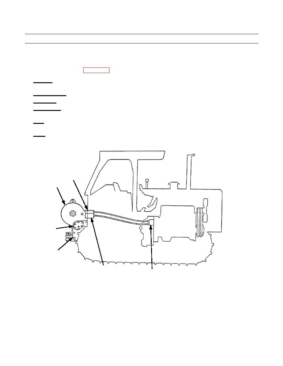
WINCH HYDRAULIC SYSTEM
NOTE
Refer to WP 0178 00 for more detailed winch theory of operation information.
1.
Reservoir. Located in the bottom of the winch case, the reservoir provides oil for the hydraulic control and lubrication
system.
2.
Magnetic Screen. Removes metal particles and other harmful debris from the oil before it reaches the pump.
3.
Gear Pump. Pulls oil from the reservoir and pushes it through the system.
4.
Control Valve. Connected mechanically by a series of linkages to the control lever in the operator station. It controls oil
pressure to the input and directional clutches.
5.
Filter. All oil flow from the pump outlet not used for clutch engagement or disengagement, or for lubrication of the winch
components, goes through the filter before returning to the reservoir.
6.
Drum. A wire rope attaches to the right side of the drum and is used to perform all types of winching operations.
MAGNETIC
SCREEN
DRUM
FILTER
RESERVOIR
CONTROL VALVE
387-056
GEAR PUMP
END OF WORK PACKAGE
0003 00-11
|
|
Privacy Statement - Press Release - Copyright Information. - Contact Us |
