|
| |
TM5-2410-237-10
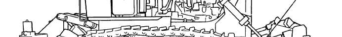
1-18. BULLDOZER HYDRAULIC SYSTEM.
BULLDOZER CONTROL VALVE. This valve is connected mechanically to the bulldozer control lever.
The valve directs the flow of pressure oil in response to the movement of the control lever.
TILT CYLINDER. This cylinder is controlled by the bulldozer control lever. When, the lever is moved to
the right, pressure oil from the hydraulic tank causes the cylinder to extend. Moving the lever to the left
causes the cylinder to retract.
LIFT CYLINDERS. These are two cylinders which are controlled by the bulldozer control lever. When
the lever is pushed forward, pressure oil causes the cylinders to extend and lower the blade. When the
lever is pulled back, the cylinders retract and raise the blade.
HYDRAULIC TANK. This is the reservoir for the oil which controls the movement of the cylinders.
1-13
|