 |
|||
|
|
|||
|
|
|||
| ||||||||||
|
|
 (3) Carry the track high enough to clear the
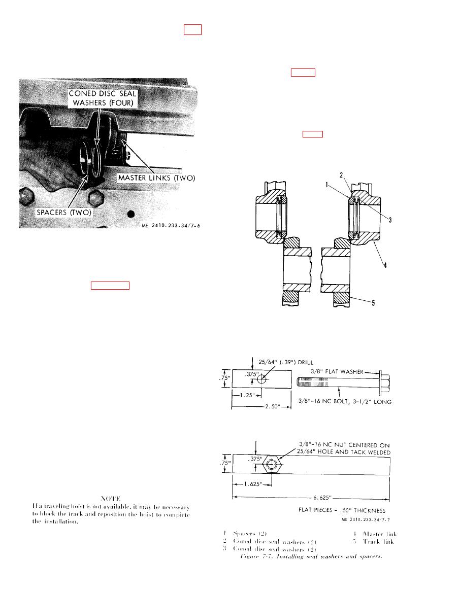
(9) Separate the track and remove spacers (fig.
rollers.
7-6) and coned disc seal washers from links.
(4) Stop with the end of the track slightly
(10) Back the machine slowly, allowing the
behind the front carrier roller and raise the other
track to ride over the carrier rollers and off the
end of the track up around front idler until the
sprocket.
master links (4, fig. 7-7) and links (5) are ap-
proximately 1 inch apart and install coned disc seal
washers (2) and (3) and spacers (1) in master links
(4).
NOTE
If the master pin is to be driven in with a sledge
hammer, block under the first shoe and drive forward
until master links (4, fig. 7-7) and links (5) are ap-
proximately 1" apart and install coned disc seal
washers (2) and (3) and spacers (1) in master links
(4).
b. Inspection and Repair.
(1) Inspect the track links and grousers for
cracks, breaks, and distortion. Repair or replace
broken or damaged links and grousers.
(2) Refer to table 1-5 for track pin and
bushing wear tolerances.
(3) Inspect the track links for wear. When the
links are worn from 4.57 to 4.38 inches in height,
they will be repaired by welding an overlay on the
wear surface. Links worn 4.38 inches or less in
height will be replaced. Link height new is 4.75
inches.
NOTE
Pin boss clearance new is 0.69 inch. Acceptable
pin boss clearance is 0.35 inch.
(4) Inspect the grousers for wear. Grousers
w o r n from 1.93-1.00 inches height will be
repaired by installing applicator bars. Grousers
worn to a height of less than 1 inch, or grousers
uneconomical to repair, will be replaced. New
grouser height is 2.56 inches. Applicator bars will
be installed one time only.
c. Reassembly and Installation.
(1) Back the tractor until the sprocket is just
ahead of the last link of the track.
(2) Attach a hoist to the outside link and raise
the track as the tractor is driven forward.
|
|
Privacy Statement - Press Release - Copyright Information. - Contact Us |
