 |
|||
|
|
|||
|
Page Title:
Figure 6-141. Installing final drive pinion gear. |
|
||
| ||||||||||
|
|
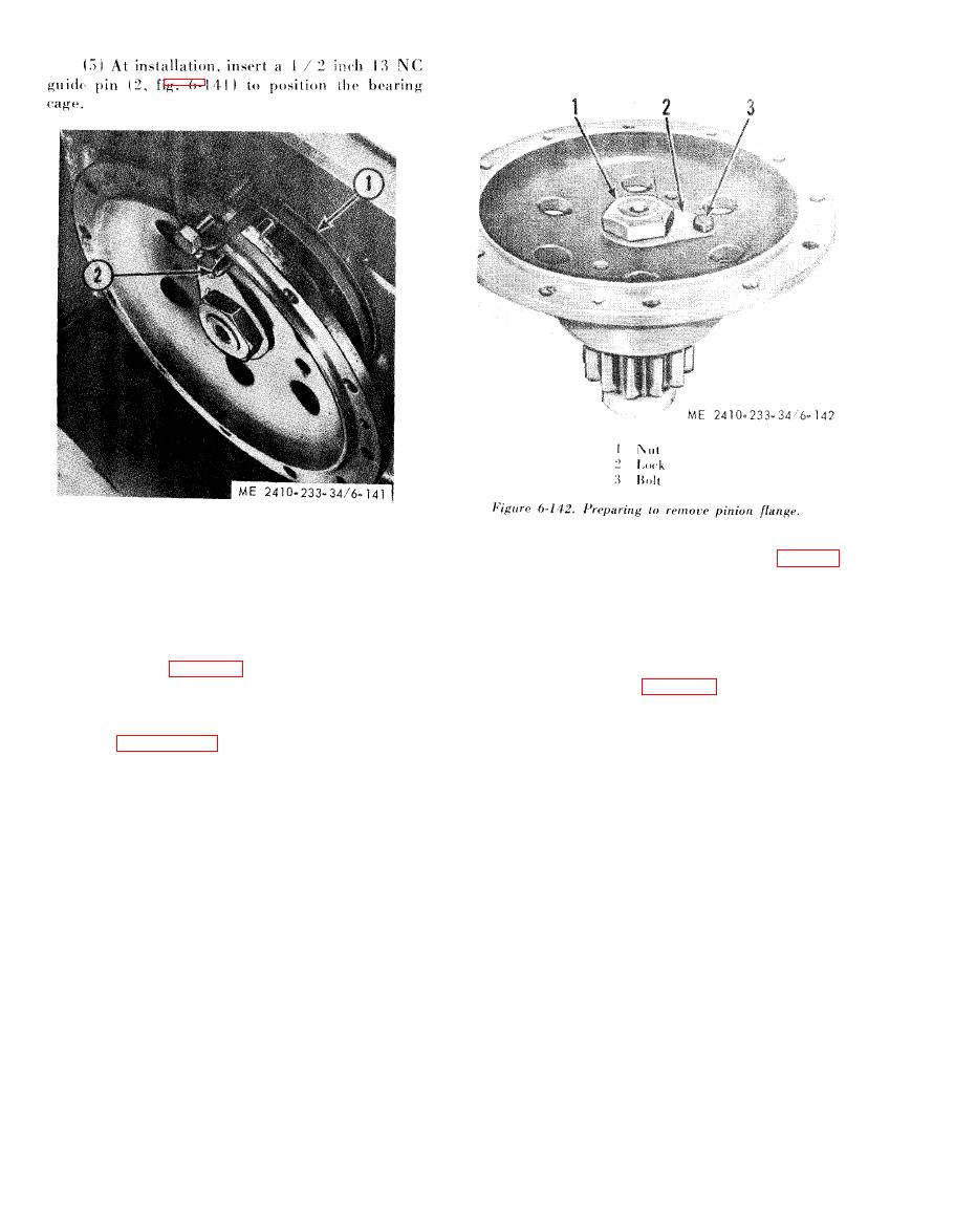 1 Gasket
CAUTION
2 Guide pin
Before attempting to remove flange (2, fig. 6-
143) install nut (1) flush with the end of the
pinion gear shaft (4) to prevent the pinion
(6) Replace gasket (1).
flange from becoming damaged while being
(7) Attach a hoist for support and install the
removed under hydraulic pressure.
final drive pinion, bearing cage and final drive
pinion flange in reverse order of removal. Position
(3) Using a hydraulic puller and a puller (with
two inch 10 NC bolts approximately 7 inches
bearing cage (1, fig. 6-140) with oil drain hole at
long) remove flange (2, fig. 6-143).
bottom.
b. Disassembly and Assembly.
NOTE
(1) Position the final drive pinion assembly as
The final drive pinion flange can be removed with the
shown in figure 6-142.
pinion installed, using the same tool group.
(2) Remove the nut (1), bolt (3), and lock (2).
|
|
Privacy Statement - Press Release - Copyright Information. - Contact Us |
