 |
|||
|
|
|||
|
|
|||
| ||||||||||
|
|
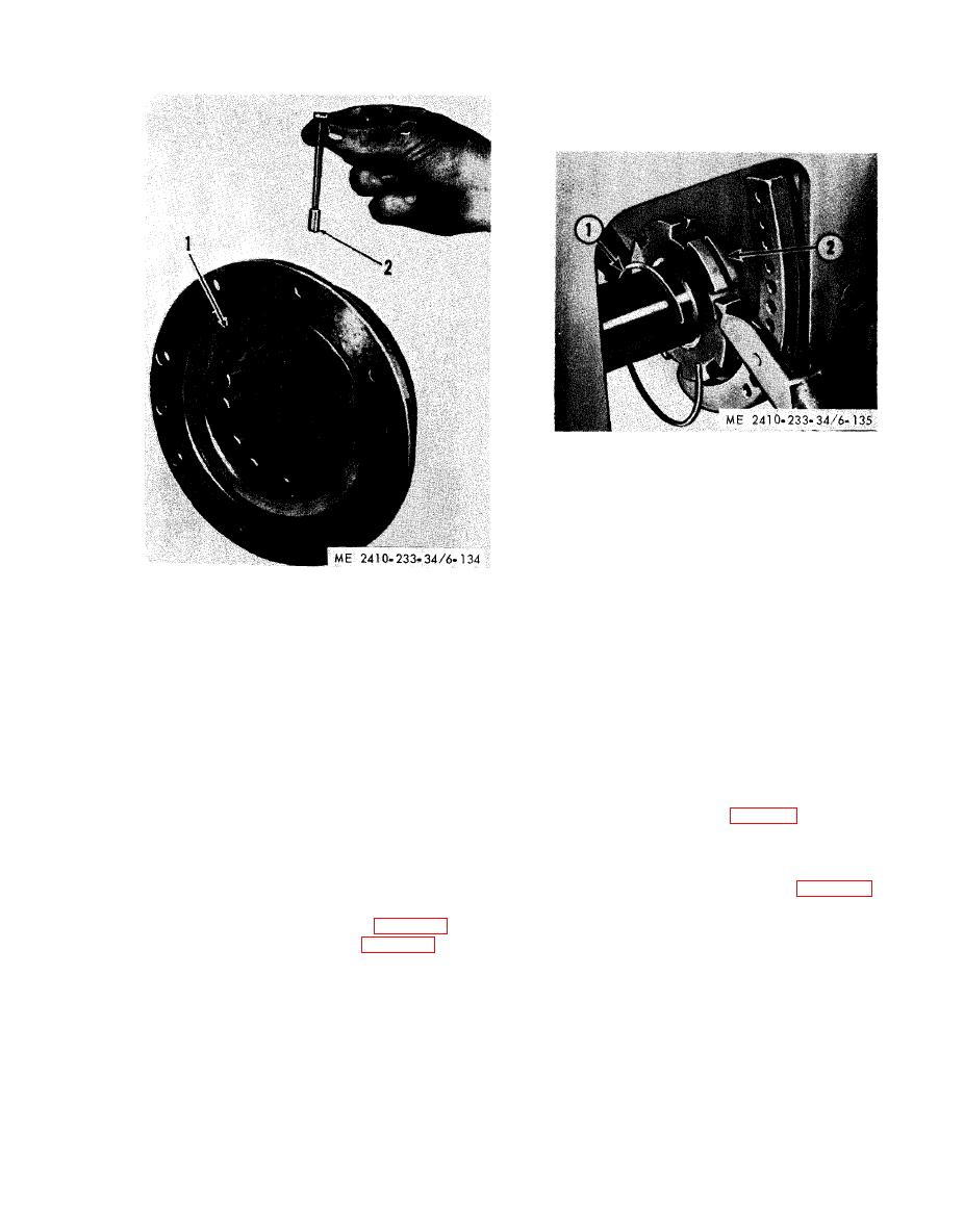 (4) Using a spanner wrench, remove the
retaining nut (2).
(5) Remove sprocket shaft.
1 Lockring
2 Retaining nut and winch removed
b. Inspection. Inspect the sprocket shaft for
dam age and distortion. Shaft must be straight
within 0.12 inch. Replace a defective sprocket
shaft.
1 Roller assembly
c. Installation.
2 Dowel
(1) Attach a hoist to sprocket shaft and
position it for installation.
(16) Inspect hub inner bearing cup (4).
(2) Position sprocket shaft retaining nut and
(17) Replace cup (4) if necessary.
lockring.
NOTE
(3) Instert sprocket shaft in the steering clutch
If the teeth of the final drive gears and pinions are
and bevel gear case far enough to install the
worn considerably more on one face than on the other,
sprocket shaft retaining nut and lockring.
they can be switched from one side of the tractor to the
(4) Place the retaining nut and lockring on the
other. This will provide a longer service life for the
shaft and install the sprocket shaft as far as possible
gears and pinions, by wearing both faces of the teeth.
into the steering clutch case.
b. Installation. Install final drive gear, idler
(5) Install adapter (3, fig. 6-136) plug (1), and
pinion and bearings in the reverse order of removal.
coupling pin (2) as shown.
NOTE
(6) Press the sprocket shaft into the steering
Heat the bearing races in oil at installation.
clutch and bevel gear case with a pressure of 55-60
6-26. Sprocket Shaft
tons. Press until dimensions (A or B, fig. 6-137) is
attained.
a. Removal.
(1) Remove final drive gear (para 6-25).
(2) Remove the locking (1, fig. 6-135).
( 3 ) Remove the pin securing sprocket
retaining nut (2) to the sprocket shaft.
|
|
Privacy Statement - Press Release - Copyright Information. - Contact Us |
