 |
|||
|
|
|||
|
Page Title:
Figure 6-129. Removing outer race and roller assemblies. |
|
||
| ||||||||||
|
|
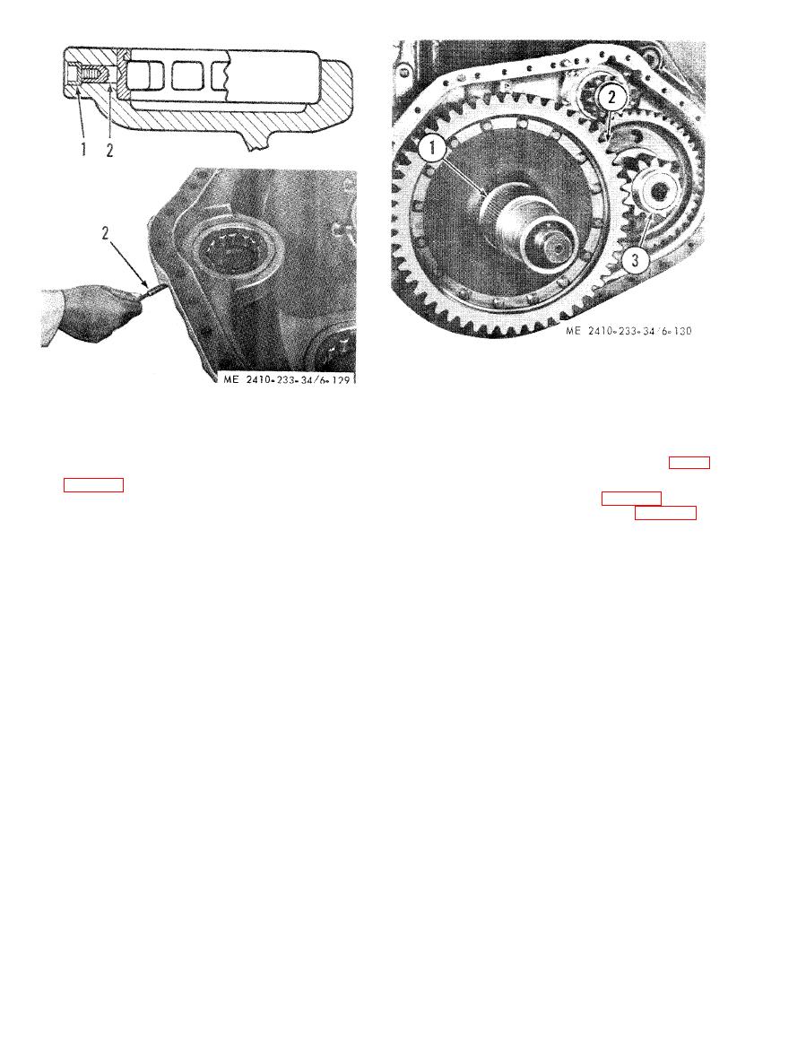 1 Hub
2 Final drive gear
3 Idler pinion
1 Plug
2 Dowel
(6) Separate gear (2) from hub (1) after
removing the bolts which hold the two together.
(7) Inspect hub inner bearing cone (5, fig. 6-
(5) Attach a hoist to support final drive gear
131).
(2, fig. 6-130) and final drive gear and hub off the
(8) Using puller assembly (4, fig. 6-132), three
sprocket shaft.
arms (1), spacer (3), cylinder group (1, fig. 6-131),
WARNING
a pump group, and an adequate spacer (3), remove
Support idler pinion (3) during removal
bearing cone (5) from the final drive hub.
of final drive gear (2) and hub (1). The
idler pinion is supported only by the
NOTE
Heat bearing cone (5) in oil at installation.
idler pinion inner bearing and is free to
fall.
|
|
Privacy Statement - Press Release - Copyright Information. - Contact Us |
