 |
|||
|
|
|||
|
Page Title:
Final Drive Gear, Idler Pinion, and Bearings |
|
||
| ||||||||||
|
|
 b. Inspection. Inspect gear cases, covers, bearing
cages, and flanges for cracks, breaks, and damaged
threads. Repair cracked or broken cases, covers, or
cages by welding and grinding smooth, or replace
the part, Repair thread damage by installing helical
inserts.
c. Installation.
(1) Install two 5/8 inch 11 NC guide pins (2,
inner races (5, fig. 6-126) with pinion outer race
and roller assemblies (6) and install the final drive
case.
(2) Install the bolts securing the final drive
case to the steering clutch case. Tighten the bolts to
the torque value given in paragraph 1-4.
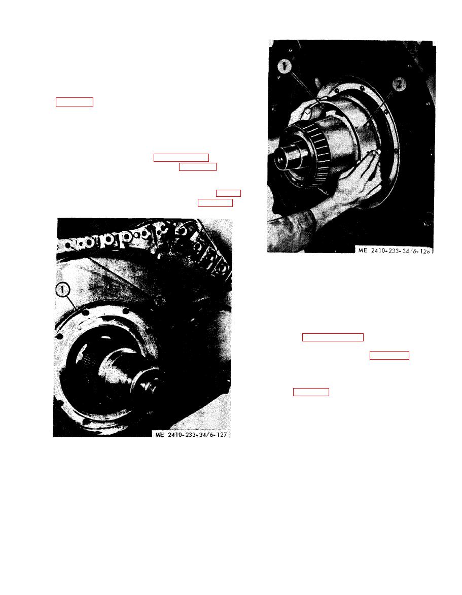
(3) Remove dirt guard (1, fig. 6-127) and
clean thoroughly so dirt will not fall on the floating
ring seals when the sprocket is installed.
(4) Install metal floating ring seal (1, fig. 6-
128) using installer tool (2) as shown (para 6-22).
1 Metal floating ring seal
2 Seal installer
Figure 6-128. Installing metal floating ring seal.
6-25. Final Drive Gear, Idler Pinion, and
a. Removal.
(4) Remove the final drive gear case as
described in paragraph 6-24.
(2) Inspect drive pinion and idler pinion outer
race and roller assemblies (6, fig. 6-126) for ex-
cessive wear.
(3) Remove both pinion outer race and roller
assemblies from the final drive case after removing
plugs (1, fig. 6-129) and dowels (2).
(4) Using a inch 20 NC bolt, remove dowel
(2) and remove pinion outer race and roller
assembly as a unit. Remove both pinion outer race
and roller assemblies in a like manner.
NOTE
All outer race and roller assemblies with snaprings are
1 Dirt guard
to be assembled with snap rings next to the gear teeth.
2 Guide pins
|
|
Privacy Statement - Press Release - Copyright Information. - Contact Us |
