 |
|||
|
|
|||
|
Page Title:
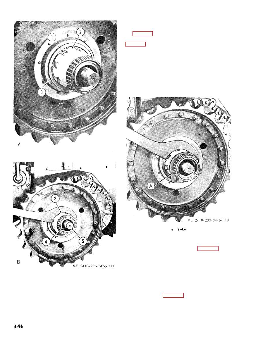
Figure 6-117. Removing outer bearing cone. |
|
||
| ||||||||||
|
|
 (c) Using a spanner wrench, back off
retaining nut (2) approximately 7/8 inch. Turn
the nut back toward the sprocket and install yoke
(A fig. 6-118) between the nut and bearing cone as
shown. Remove hearing cone by unscrewing nut (2,
CAUTION
After the outer bearing cone has been
forced off, install sprocket retaining nut
(2) on the final drive hub, leaving ap-
p r o x i m a t e l y 1/4 inch clearance be-
tween the retaining nut and sprocket.
This will keep the sprocket from
jumping off final drive hub (5) during
pulling.
Figure 6-118. Removing nut witk yoke installed.
(d) Attach the Cylinder Group to the Pump
Group. Place sleeve assembly (5, fig. 6-119) over
the sprocket shaft and against final drive gear hub.
Attach the cylinder group to the sprocket with arms
(2), adapters and nuts (4) and pins (3) and pull the
sprocket loose from hub.
(e) Relieve the pressure on the cylinder
1
Lock
group and remove puller arrangement from the
2
Bearing nut
sprocket.
3
Metal floating ring seal
(f) Attach a hoist to the sprocket and remove
4
Bearing cone
5
Final drive hub
retaining nut (2, fig. 6-117) and lock (1).
(g) Remove sprocket (weight approximately
300 lb).
|
|
Privacy Statement - Press Release - Copyright Information. - Contact Us |