 |
|||
|
|
|||
|
Page Title:
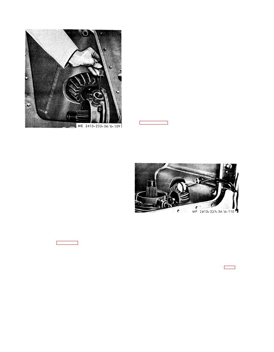
Figure 6-109. Measuring clearance. |
|
||
| ||||||||||
|
|
 (d) U s e a t h i c k n e s s g a g e t o d e t e r m i n e t h e
clearance between the flange of the bearing cage
and the face of the bevel gear case at each bolt
l o c a t i o n making sure the clearance-is the same all
around the cage.
(e) R e m o v e t h e c a g e a n d i n s t a l l t h e s h i m s
with a total thickness the same as the clearance
d e t e r m i n e d in subpara (4) less 0.015 inch to give
the required preload to the bevel gear shaft
bearings.
NOTE
THe 0.015 inch shim removal includes 0.002 inch end
clearance as left in (c) above, plus the 0.013 inch
normal preload.
(f) A g a i n i n s t a l l t h e c a g e a n d l o c k w a s h e r s
and securely tighten the bolts.
(4) B a c k l a s h a d j u s t m e n t .
( a ) Mount a dial indicator with a universal
attachment on one of the pinion gear teeth as shown
(b) B l o c k t h e b e v e l g e a r .
(c) Move the pinion as far forward as
p o s s i b l e and rock the pinion gear back and forth.
(f) Remove the cage and install shims with a
The backlash between the bevel gear and pinion
total thickness the same as the measured clearance,
will be the difference in readings on the dial in-
Install the cage and tighten the bolts.
dicator.
(g) R e c h e c k t h e t o r q u e r e q u i r e d t o r o t a t e
the bevel gear shaft.
(h) After the transmission is in place, adjust
t h e backlash as described in (4) below, moving the
s h i m s from one cage to the other as required, but
not changing the total number of shims.
(3) Bevel gear shaft adjustment (transmission
installed).
NOTE
If the transmission is in place and it is not feasible to
remove it, the bevel gear shaft bearings can be
preloaded in the following manner. An approximate
adjustment for backlash can be made at the same time.
(a) Install enough shims behind the bearing
(d) Check the backlash at four points
cage nearer the bevel gear to give approximately the
around the bevel gear to determine the point of
amount of backlash indicated on the end of the
l e a s t backlash. Be sure the pinion is held forward
b e v e l pinion or in table 1-4.
while rocking it back and forth to take the backlash
(b) I n s t a l l t h e o t h e r b e a r i n g c a g e w i t h o u t
readings.
s h i m s or lockwashers and tighten the bolts evenly
NOTE
w h i l e slowly rotating the bevel gear until a definite
The correct amount of backlash is marked at the end
of the bevel pinion, if installedin the machine at the
preload is noticeable on the bevel gear shaft
factory. If the bevel pinion is not marked, refer to table
bearings.
1-4.
(c) Evenly back off the bolts on the bearing
(e) If the reading is too great at the point of
c a g e without shims until approximately 0.002 inch
l e a s t backlash, remove shims from the bearing cage
end clearance has been reached on the bevel gear
o n the right side and install them on the left side.
shaft, being sure there is backlash between the
NOTE
bevel gear and pinion.
THe preload on the bevel gear shaft bearings will not
NOTE
be changed by moving shims from one side to the other
To determine end clearance, pry against the ends of
if the same total number of shims is maintained.
the bevel gear shaft.
(f) T o i n c r e a s e t h e b a c k l a s h , m o v e s h i m s
f r o m the left side to the right side.
|
|
Privacy Statement - Press Release - Copyright Information. - Contact Us |
