 |
|||
|
|
|||
|
|
|||
| ||||||||||
|
|
 roughness, and wear. Replace worn or defective
(7) Attach a suitable hoist to support the bevel
bearings.
gear shaft.
(2) Inspect the bevel gear and pinion for
(8) Remove bolts (2), and remove bearing
chipped, pitted, broken or worn teeth. Replace a
c a g e (3) using two 1/2 i n c h 1 3 ( N C ) f o r c i n g s c r e w s
damaged or excessively worn gear set. TB-ENG
(4) as shown.
364 may be used as a guide for determining gear
(9) Slide the bevel gear (1, fig. 6-106) and the
replacement.
bevel gear shaft (5) out of the left bearing cage, far
e n o u g h to permit removal of bolts (4) securing the
(3) Inspect the bearing cages for cracks,
breaks, and other damage. Replace defective or
b e v e l gear (1) to the flange on the bevel gear shaft
(5).
damaged bearing cages.
d. Bevel Gear and Pinion Setting.
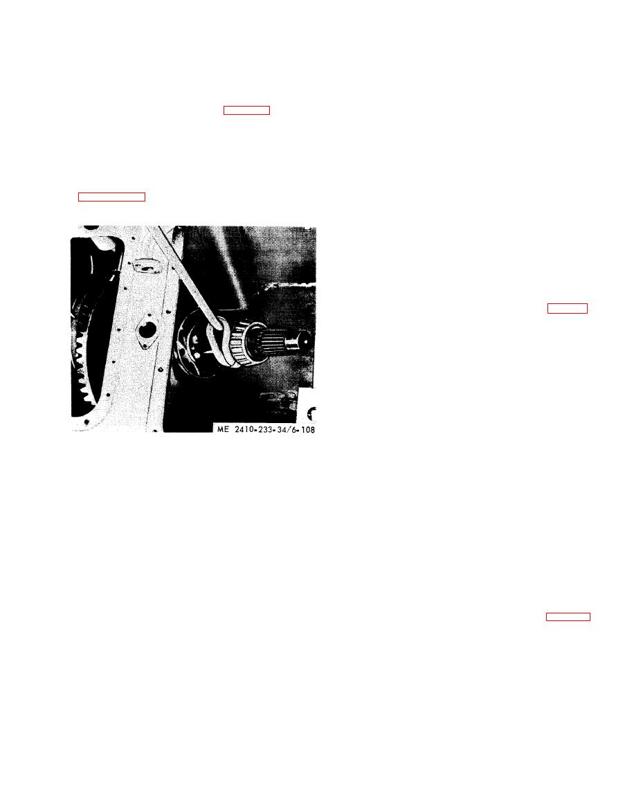
( 1 0 ) Move the bevel gear shaft into the right
(1) G e n e r a l . The bevel pinion is free to float in
s t e e r i n g clutch compartment and lift out as shown
the transfer case of the transmission and seeks its
o w n running position with respect to the bevel gear
(11) Lift out the bevel gear.
in forward speeds, and is located by the rear
b e a r i n g in reverse. The only adjustments necessary
a r e the bevel gear shaft bearing preload (subpara 2
a n d 3 below), and the backlash (subpara 4 below),
between the bevel gear and pinion. The correct
a m o u n t of backlash for each bevel pinion, installed
at the factory, is marked on the end of the bevel
pinion. If the pinion is not marked, refer to table 1-
4. After adjusting the bevel gear shaft bearing
p r e l o a d , t h e b a c k l a s h s h o u l d b e set as described
below.
(2) B e v e l g e a r s h a f t bearing adjustment
(transmission removed).
NOTE
It is preferred that the bevel gear shrift bearing preload
be set with the transmission removed. This permits
adjusting the bearings to a definite preload.
(a) Install a full shim pack under the
bearing cage farther from the bevel gear. Tighten
all bolts.
(12) Install the bevel gear and shaft in the
(b) I n s t a l l t h e o t h e r b e a r i n g c a g e w i t h o u t
r e v e r s e order of removal. Adjust the bevel gear and
shims and tighten the bolts evenly while slowly
pinion backlash as described in subparagraph d
rotating the bevel gear until a torque, given in table
below.
1 - 4 is required to rotate it.
b. Disassembly and Reassembly.
(c) R o t a t e t h e b e v e l g e a r s h a f t b e a r i n g s
several times before making the final adjustment.
(1) Remove the bearing cones from the shaft
w i t h a hydraulic puller, a puller, a bearing pulling
(d) To determine the torque required to
attachment and a step plate.
rotate the shaft, weld a strap of metal across a
(2) Heat the bearing cones in oil prior to
s t e e r i n g clutch hub retaining nut and weld a small
reassembly,
n u t on the strap; then thread the retaining nut onto
t h e bevel gear shaft, and apply a torque wrench to
(3) Remove the cups from the bearing
cages using a puller, two adapters and a bearing cup
the small nut.
pulling attachment with an adapter,
(4)
Chill
the
cups
in
dry
ice
prior
to
1 0 9 to determine the clearance between the flange
reassembly.
o f the bearing cage and the face of the bevel gear
c. lnspection and Repair.
c a s e at each bolt location making sure the clearance
(1) Inspect all bearings for corrosion,
is the same all around the cage.
|
|
Privacy Statement - Press Release - Copyright Information. - Contact Us |
