 |
|||
|
|
|||
|
Page Title:
Figure 6-104. Control lever housing disassembly. |
|
||
| ||||||||||
|
|
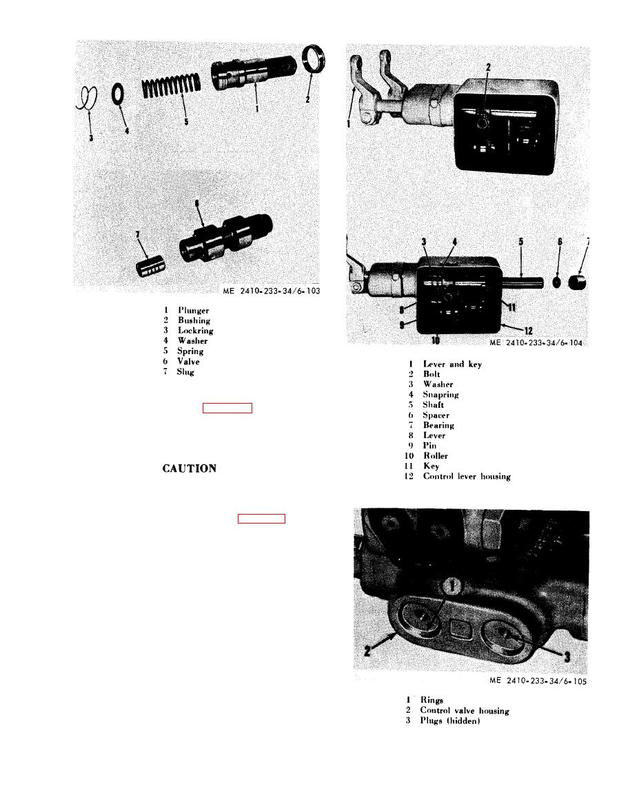 (4) Remove slugs (7, fig. 6-103) from both
valves (6).
(5) Replace worn or damaged parts and
assemble valves and plungers back into housing in
reverse order of removal.
Extreme care should be taken to avoid
introducing dirt into the housing when
a s s e m b l i n g the plungers and valves.
(6) Remove lever and key (1, fig. 6-104) and
loosen bolt (2).
(7) Tap end of shaft (5) to remove spacer (6)
and bearing (7) from control lever housing (12).
(8) Remove snapring (4).
(9) Remove washer (3), lever (8) and key (11)
while pulling shaft from housing.
(10) Remove pin (9) and roller (10).
( 1 1 ) Remove seal and bearing from control
lever end of housing.
NOTE
Seal should be installed with lip facing inward.
|
|
Privacy Statement - Press Release - Copyright Information. - Contact Us |
