 |
|||
|
|
|||
|
Page Title:
Figure 6-91. Compressing steering clutch springs. |
|
||
| ||||||||||
|
|
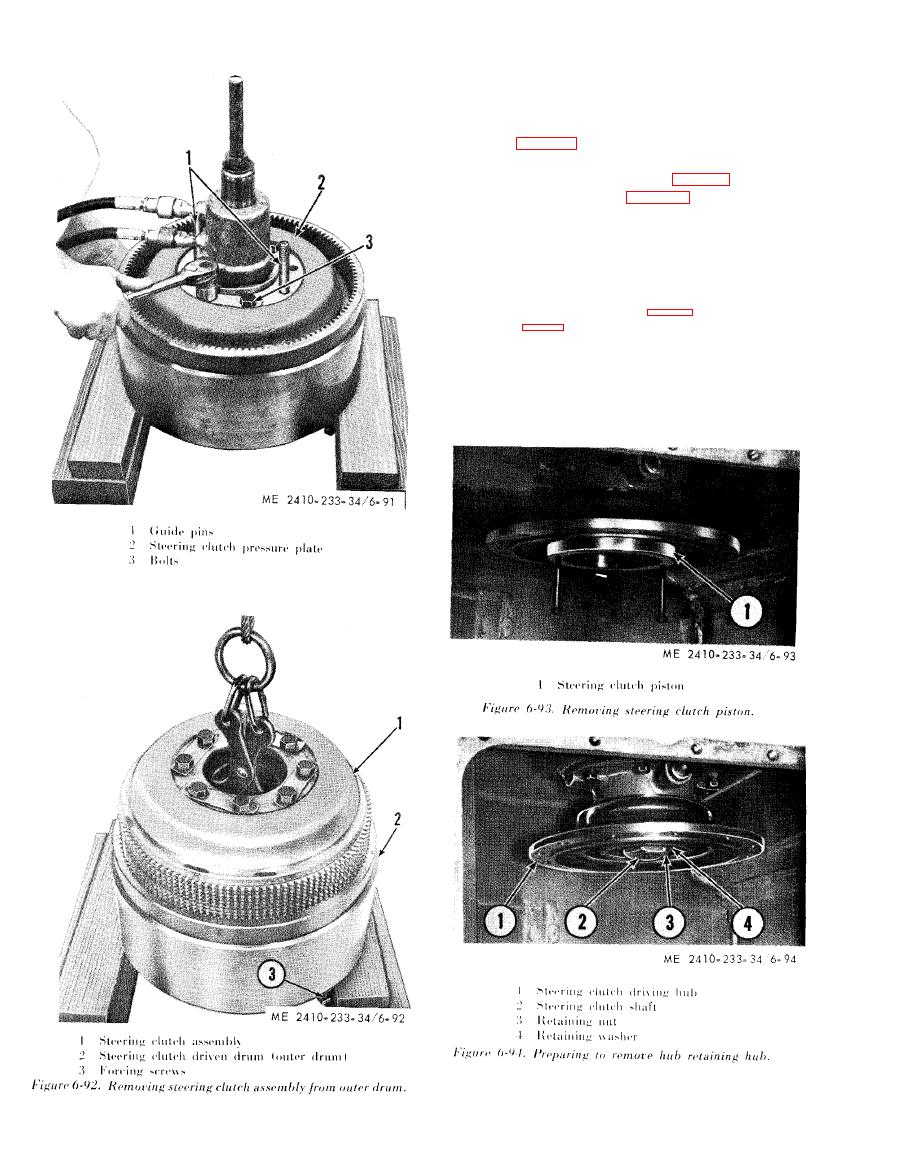 6-16. Steering Clutch Driving Hub
a. Removal.
(1) Install two 5 / 16 inch 18 (NC) bolts
a p p r o x i m a t e l y 3 inches long in the steering clutch
p i s t o n (1, fig. 6-93). Remove the piston by pulling
toward the outside of the tractor.
( 2 ) Straighten the lock (11, fig. 6-96) securing
the hub retaining nut (3, fig. 6-94).
(3) Remove the retaining nut (3).
NOTE
To facilitate nut removal, with both steering clutches
5
removed,
install
two
/ 8i n c h - 1 1 ( N C ) b o l t s ( 1 , f i g . 6 -
95)
approximately
3
inches
long,
into
the
opposite
clutch hub clearance holes a n d
insert
a
bar
to
retain
the
steering
clutch
shaft
(2.
Using
the
wrench
(2.
6-95)
remove
the
retaining
nut.
This
procedure can be
used
when
installing
the
retaining
nut, after placing the opposite clutch hub on the shaft
temporarily,
and
inserting
the
bolts
(1)
to
retain
the
clutch
shaft.
With
one
sterring
clutch
removed,
the
clutch
shaft
can
be
retained
by
applying
the
opposite
brake.
|
|
Privacy Statement - Press Release - Copyright Information. - Contact Us |
