 |
|||
|
|
|||
|
Page Title:
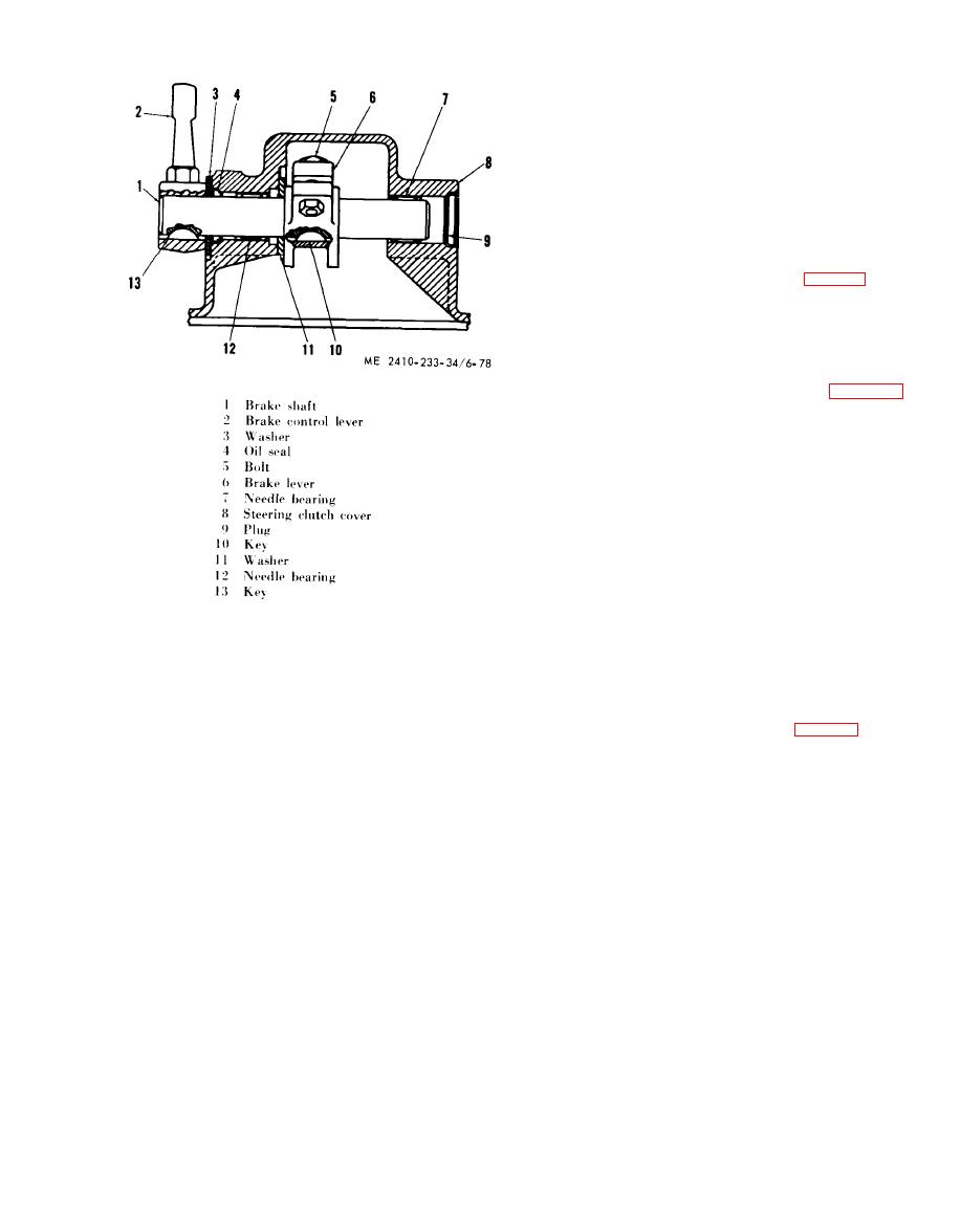
Figure 6-78. Disassembling clutch cover brake linkage. |
|
||
| ||||||||||
|
|
 (5)
Inspect
the
brake
drums
for
scoring,
dam age and
wear.
Replace
a
damaged,
badly
scored, or excessively worn drum.
NOTE
Steeering brake drums which are not scored, cracked, or
otherwise damaged, may be considered serviceable
from the wear standpoint, if the following conditions is
met: after installing new brake linings, at least one
half of the band adjustment travel must remain. If one
half or more of the adjustment travel does not remain.
replace the drum.
(6) Inspect washers (3) and (11), fig. 6-78, for
dam age and wear. Replace if damaged or worn
excessively.
( 7 ) Inspect all springs for cracks, breaks, and
distortion. Replace defective springs.
e. Adjustment.
( 1 ) Install a wood block as shown in figure 6-
7 9 and turn the adjusting screw clockwise until the
lever assemblies are firmly against their stops.
(2)
Lift
brake
link
with
a
pull
of
ap-
proximately 30 pounds.
( 3 ) Measure the distance "A" from the top of
the pin, which joins the brake link to the brake
toggle links, to the milled flat on the support
assembly.
(4) Add or remove shims behind the stop to
o b t a i n a distance "A" of 0.860 inch to 0.900 inch.
( 5 ) Install the support assembly in the steering
clutch and bevel gear case (subpara a a b o v e ) .
(6) Turn the adjusting screw socket assembly
d. Inspection and Repair.
u n t i l the brake band is tight on the steering clutch
( 1 ) Inspect all supports, links, levers, and pins
o u t e r drum. Back off the socket assembly 1 1/2 t u r n s
for cracks, breaks, distortion and wear. Repair by
or nine clicks.
welding, straightening, or replace the part.
(7) Install the remaining brake linkage.
(2) Inspect all needle bearings for corrosion,
( 8 ) The parking brake lever (1, fig. 6-80) can
roughness, and wear. Replace damaged or ex-
be adjusted by disengaging the parking brake and
cessively worn bearings.
adjusting the parking brake linkage (4) to obtain
( 3 ) Inspect all sleeve bearings for damage and
dimension (B), which is the distance between the
wear. Sleeve bearing to pin clearance (new) is
front face of the seat arm rest support and cen-
approximately 0.003 to 0.005 inch. The maximum
t e r l i n e of parking brake lever (0.82 to 0.94 inches).
clearance is 0 . 0 1 5 i n c h . Replace
allowable
T h e brake pedal (2) can be adjusted by disengaging
damaged or excessively worn bearings or pins.
the parking brake and adjusting the brake linkage
(4) Inspect the brake linings for damaged or
( 3 ) to dimension (C) which is the distance between
w o r n condition. Replace the linings if damaged or
t h e front face of the seat support and the rear face
w o r n to within 3 / 32 inch of rivet heads.
of the brake pedal (17.63 to 17.87 inches).
|
|
Privacy Statement - Press Release - Copyright Information. - Contact Us |
