 |
|||
|
|
|||
|
Page Title:
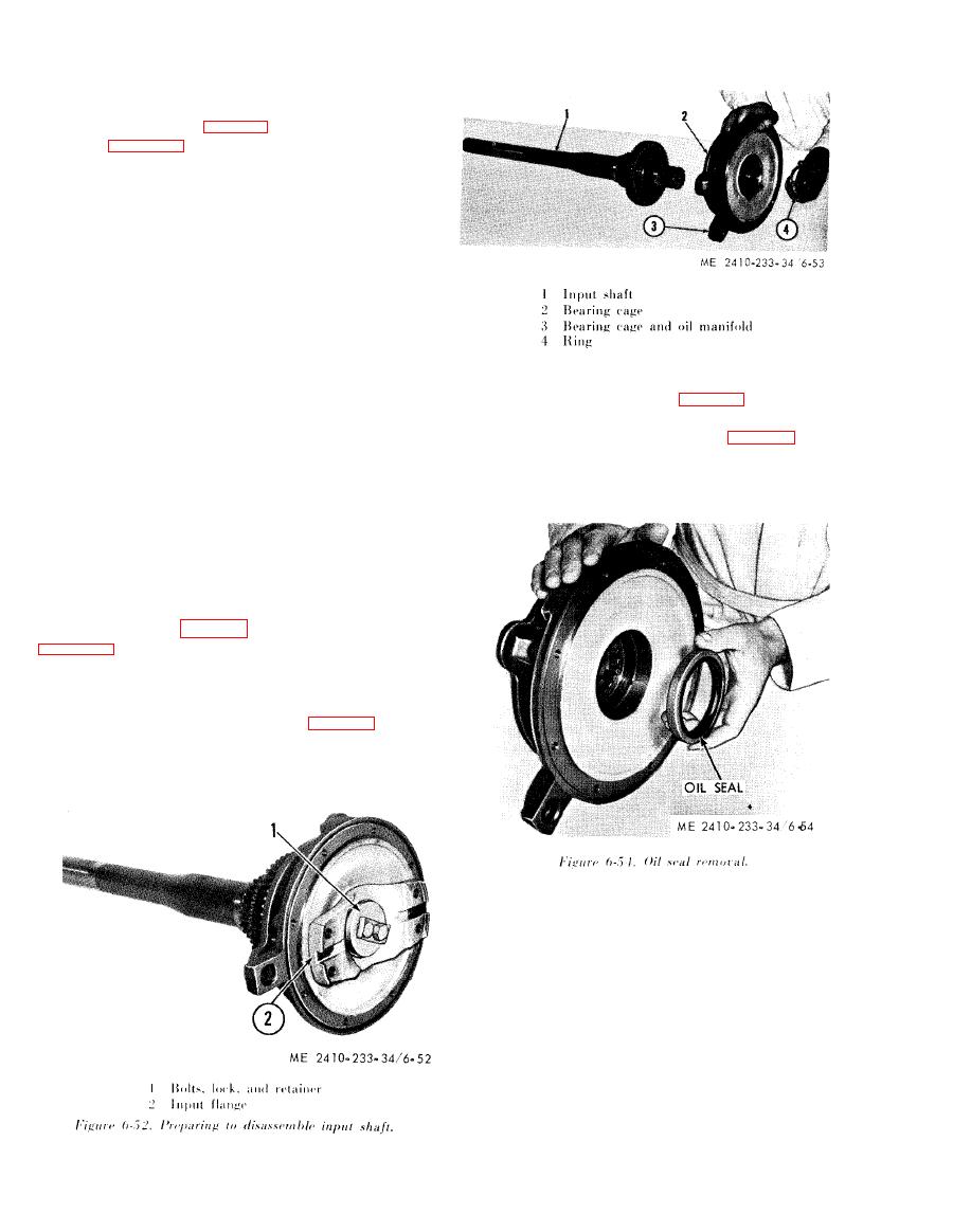
Figure 6-53. Bearing cage removal. |
|
||
| ||||||||||
|
|
 (11) Inspect and replace all worn parts before
assembling
the transmission. At the time of
assembly tighten the No. 2 carrier to bearing cage,
retaining bolts (2, 3, fig. 6-50) to the torque value
listed in table 1-2.
(12) All worn, damaged, or warped clutch
plates and disc assemblies should be replaced when
i n s t a l l i n g the clutches.
CAUTION
When installing the clutches, install the
c l u t c h housing first, then install the ring
gear
followed
by
a
disc
assembly
and
plate alternately (subpara j below) for
the correct number of disc assemblies
and plates for each clutch. Make certain
the clutch reaction pins are in their
proper location and the springs are
seated correctly. The ring gear for the
(3) Remove the oil seal (fig. 6-54) by tapping
No. 5 clutch should be installed with the
it from the rear with a small block of wood.
face having the smaller outer diameter
(4) Remove the retainer ring (fig. 6-55).
t o w a r d t h e i n p u t e n d of the trans-
NOTE
mission. The clutch housing for the No.
The
oil
seal
is
correctly
installed
with
the
spring-loaded
1
clutch
is i n s t a l l e d i n v e r t e d
with
lip toward the rear of the the transmission.
respect
to
other
clutches.
the
In-
stallation of the clutch housings can be
facilitated by using three of the long
retaining bolts as guide pins.
( 1 3 ) Complete the installation in the reverse
order of removal and tighten the clutch housing
r e t a i n i n g bolts (1, fig. 6 - 4 7 ) to the value given in
g. Input Shaft Disassembly and Assembly.
(1) Remove bolts, lock, and retainer (1, fig. 6-
52), and input flange (2).
( 2 ) Slide the bearing cage (2, fig. 6-53) and
b e a r i n g cage and oil manifold (3) from the input
s h a f t (1) while removing the ring (4) at the same
time.
|
|
Privacy Statement - Press Release - Copyright Information. - Contact Us |
