 |
|||
|
|
|||
|
Page Title:
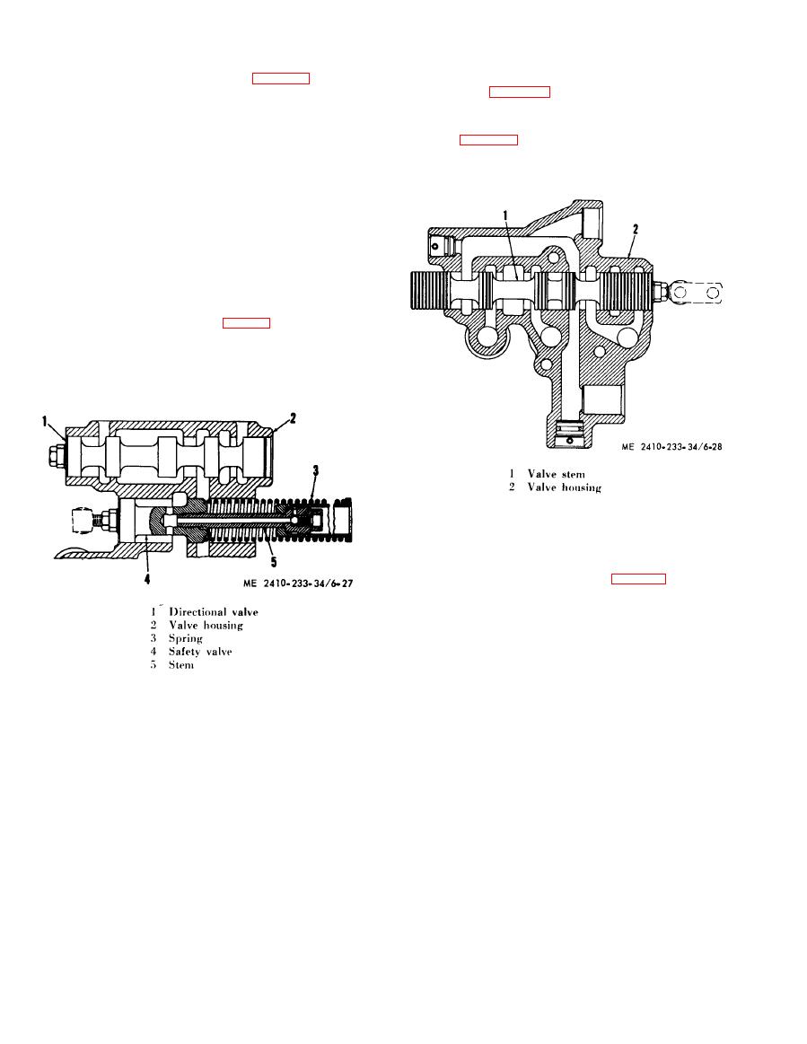
Figure 6-27. Safety and directional valve disassembly. |
|
||
| ||||||||||
|
|
 L i q u i d Lock on threads of valve stem (5), install
(3) P r e s s u r e c o n t r o l v a l v e r e a s s e m b l y .
valve stem into valve (4), and tighten to torque
v a l u e listed in table 1-2. Do not hold valve (4) by
(13), and retainer (12), into piston (15), and secure
finished lands.
i n place with retainer ring (11).
(5) Speed selector valve. S p e e d s e l e c t o r v a l v e
(b) I n s t a l l s l u g ( 1 0 ) i n t o p i s t o n ( 1 5 ) .
stem (1, fig. 6-28) can be removed from valve
(c) Install pistons (2) and (15) and stops
housing (2) if necessary.
(1), (9), and (16), into housing (3). Secure stops in
d.
Linkage
Adjustment.
place with pins.
(d) Install piston (6), retainer (5), and
piston (18), into housing (7).
NOTE
Install
spacers
(19)
inside
piston
(18).
(e) With
springs
(4)
and
(17)
in
their
proper location, f a s t e n h o u s i n g s ( 3 ) a n d ( 7 )
together with bolts (20) through cover (8).
(4) S a f e t y a n d d i r e c t i o n a l v a l v e .
(a) S a f e t y v a l v e ( 4 , f i g . 6 - 2 7 ) a n d d i r e c -
tional valve (1) can be removed from valve housing
(2) for inspection.
(b) S c r e w c e n t e r s t e m o u t o f v a l v e ( 4 ) t o
remove spring (3).
(1) I n t e r n a l a d j u s t m e n t ,
(a) When hydraulic controls are installed in
t r a n s m i s s i o n , control linkage should be adjusted to
position directional valve stem (5, fig. 6-29), safety
stem (3) and speed selector valve stem (2) properly
i n their selective housings.
shown, adjust threaded drag links in ends of valve
stems so end of first land of each valve is flush with
machined face of valve housing; the end of first
l a n d of valve stem (2) must be flush with surface
( A ) , (3) with surface (B), and (5) with surface (C).
CAUTION
(2) E x t e r n a l a d j u s t m e n t .
Valve stem (5) may be thrown with
WARNING
considerable force by spring (3) when
Do not adjust linkage with engine
threads
are
disengaged.
running.
(c) When assembling safety valve, apply
|
|
Privacy Statement - Press Release - Copyright Information. - Contact Us |
