 |
|||
|
|
|||
|
Page Title:
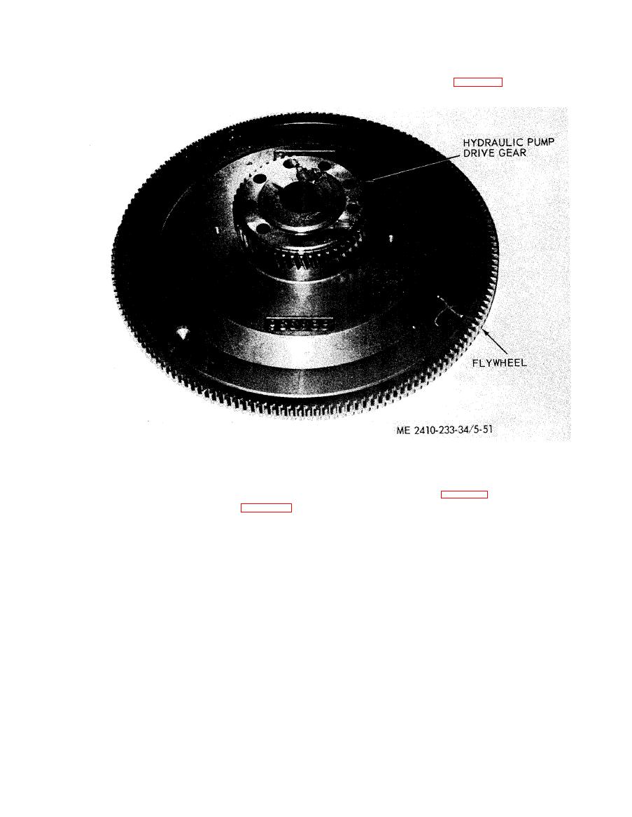
Figure 5-51. Flywheel and hydraulic pump drive gear. |
|
||
| ||||||||||
|
|
 CAUTION
(6) Install a inch - 13NC forged eyebolt
Keep the flywheel level during removal
in the flywheel. Attach a hoist and remove the
in order to prevent gear from falling off
flywheel.
front of flywheel (fig. 5-51).
( 1 0 ) R e m o v e t h e h y d r a u l i c p u m p d r i v e i d ler
(7) Remove the hydraulic pump drive gear
f r o m front of flywheel.
g e a r r e t a i n i n g b o l t s ( f i g . 5 - 5 2 ) a n d l o c k . R e m o ve
t h e idler gear and shaft.
(8) Remove the oil pan plate (para 5-24).
(9) Remove transmission oil pump (TM 5-
2410-233-20).
|
|
Privacy Statement - Press Release - Copyright Information. - Contact Us |
