 |
|||
|
|
|||
|
|
|||
| ||||||||||
|
|
 scoring, scratches, grooves or wear. Replace if worn
(3) Compensate for worn timing gears by
or damaged. Measure the camshaft bearing sur-
a d j u s t i n g the fuel injection pump lifters (para 5-
f a c e s using a micrometer. If any diameter is less
11).
than 1.40 inches, replace the camshaft.
( 4 ) If the backlash measurement is low, check
f o r a burr or rough spot on one of the gears a n d
(3) Inspect the camshaft bearings for wear
a n d s u r f a c e d a m a g e . R e p a i r if possible or replace
s m o o t h as required.
b e a r i n g s as required.
5-30. Cam shaft
(4) Inspect the camshaft gear for broken
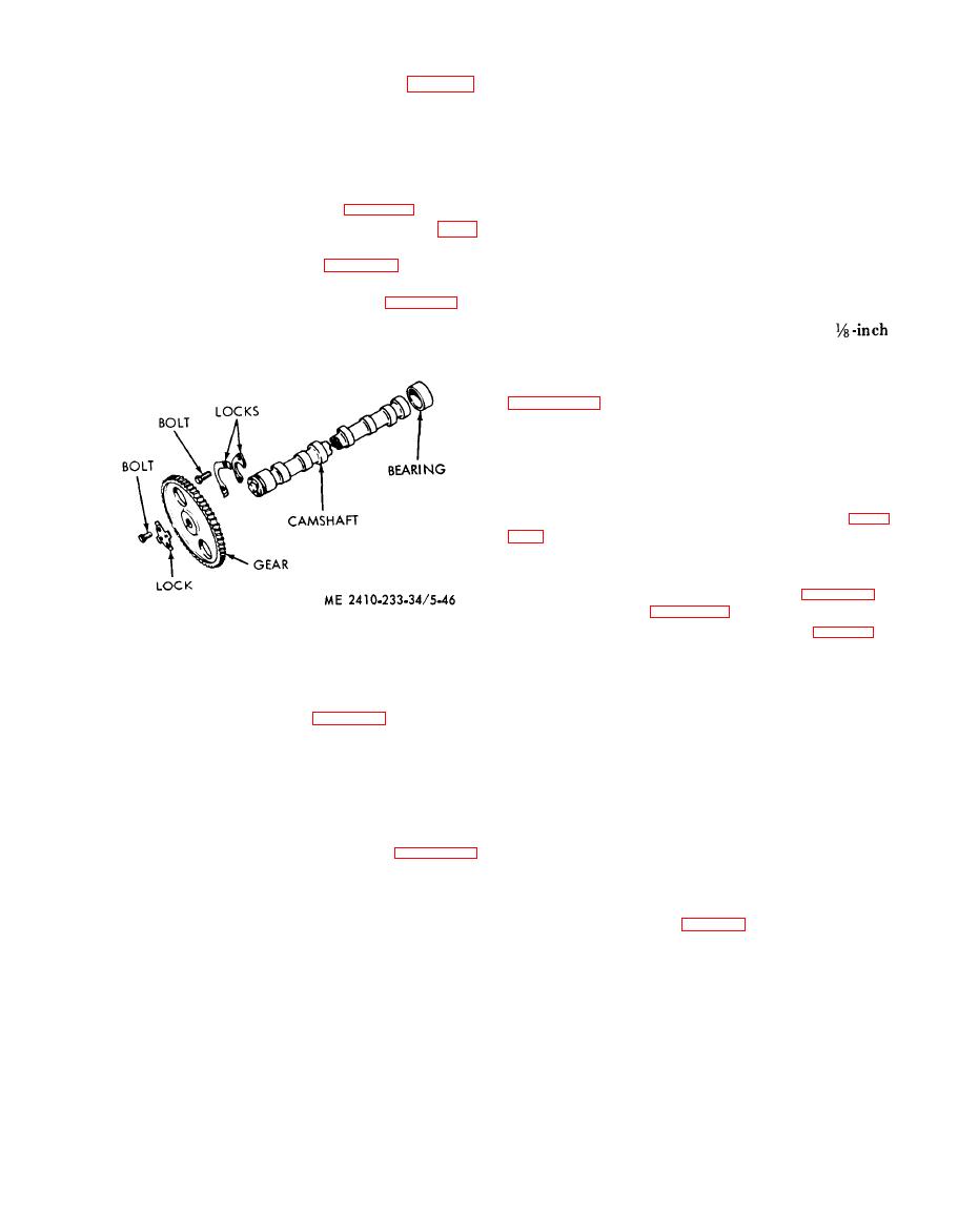
a. Removal and Disassembly (fig. 5-46).
t e e t h , cracks, scratches, scoring and wear. Repair
( 1 ) Remove the engine from the tractor
o r replace as required.
2-8).
d. Reassembly and Installation.
( 2 ) Remove the pushrods (para 5-27) and lift
(1) Install the camshaft bearings in the
t h e valve lifters clear of the camshaft.
cylinder block. Align the oil holes in the front
( 3 ) Remove the timing gear cover (para 5-29).
b e a r i n g with the oil hole in the block. Install the
(4) Remove two bolts and the washer and pull
f r o n t and rear bearings so that there is a
the camshaft and camshaft gear from the block. Be
clearance
between
the
cylinder
block
and
the
c a r e f u l not to damage the camshaft bearings.
bearing.
(2) Install the flywheel housing, if removed
(3) Install the gear to the camshaft. Secure
w i t h the lock and four bolts.
( 4 ) Install the camshaft and camshaft gear in
the block and secure with the washers and two
bolts.
( 5 ) Check the camshaft gears backlash (para
(6) Check
the
camshaft
end
clearance
(subpara e).
( 7 ) Install the timing gear cover (para 5-29)
and the pushrods (para 5-27).
(8) Install the engine in the grader (para 2-8).
e. Checking Camshaft End Clearance.
(5) Remove four bolts and the lock and pull
(1) Push the
washer
forward
against
the
t h e gear from the camshaft.
cam shaft gear.
(6) If camshaft bearings are to be removed,
(2) Using a thickness gage, measure the
r e m o v e the flywheel housing (para 5-31) and press
distance between the washer and the end of the
t h e bearings out of the block.
c a m s h a f t bearing journal. The clearance should be
b. Cleaning.
0.004 to 0.010 inch and must not exceed 0.025
(1) Clean the camshaft thoroughly with
inch.
cleaning solvent (Fed. Spec. P-D-680). Blow out
Power
Take-Off
Drive
Gears
and
t h e oil holes with compressed air. Dry with clean,
Bearings
l i n t - f r e e cloths or with compressed air.
a. Removal.
( 2 ) Clean bearings as instructed in paragraph
(1) Remove transmission oil pump, winch
2-6.
hydraulic pump, and bulldozer hydraulic pump
c. I n s p e c t i o n
and
Repair.
(TM
5-2410-233-20).
(1) Using a magnetic particle technique,
( 2 ) Remove bolts (fig. 5-47) and remove cover
inspect the camshaft for cracks. Replace if any
f r o m flywheel housing. Remove the thrust washers
c r a c k s are detected.
from the cover assembly.
(2) Inspect the
camshaft
for
roughness,
|
|
Privacy Statement - Press Release - Copyright Information. - Contact Us |
