 |
|||
|
|
|||
|
|
|||
| ||||||||||
|
|
 c. lnstallation. Reverse removal procedure and
install the exhaust manifold on engine.
manifold for cracks, broken mounting flanges, or
other damage. Weld cracks and other minor
damage according to TM 9-237. Replace an ex-
cessively damaged exhaust manifold.
Section IV. ELECTRICAL SYSTEM
5-19. General
(13) Remove dowel pins (9) only if they
require replacement.
The tractor electrical system supplies the power to
(14) Remove screw (45). Remove four screws
start the engine and operate the lights and in-
(21), receptacle connector (22) and leads (27) and
struments. The system consists of batteries,
(28).
Remove leads only if they require
replacement.
switches, and other electrical components. Refer to
(15) Remove four screws (23), elbow (24)
and elbow spacer (26).
5-20. Generator
(16) If coil assemblies (20), (38), (39) and
(41) require replacement, remove two screws (17)
am pere type mounted on the right-front of the
securing each pole shoe (18) to housing. Remove
engine. It is fungus and corrosion resistant and is
pole shoes, windings and insulators (19).
arranged for B-type circuit with the field grounded
d. Cleaning.
inside the generator.
(1) Clean the armature and field windings of
b. Removal. Refer to TM 5-2410-233-20 for
any dirt or magnetized particles. To remove grease
the removal of the generator.
and oil, apply a light coat of cleaning solvent (Fed.
c. Disassembly.
Spec. P-D-68) with a brush. Wipe clean, then use
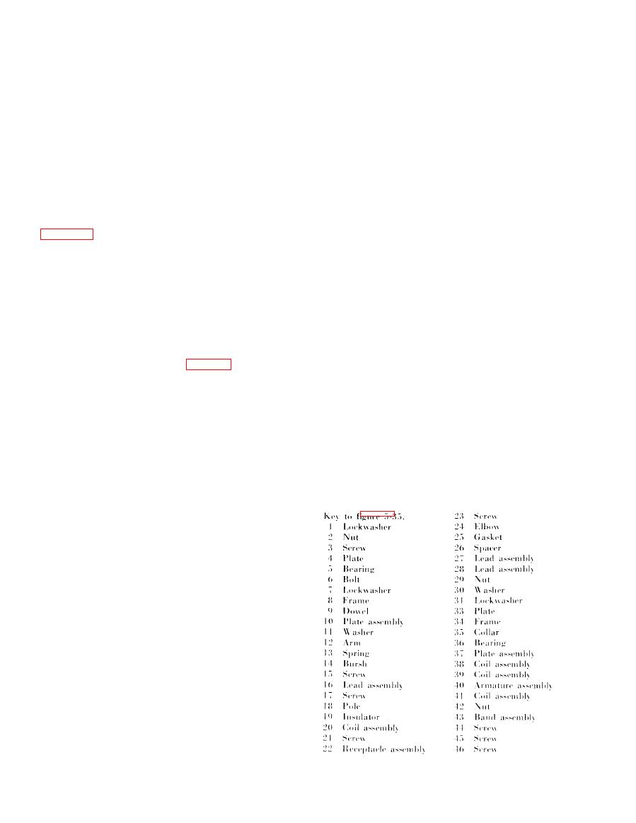
(1) Remove nut ((29), fig. 5-35) flat washer
compressed air to remove any remaining dirt film.
(30) and collar (35).
Do not use any decreasing compounds or submerge
(2) Remove screw (44), nut (42) and cover
the armature in a degreasing tank as this would
band (43).
damage the insulation.
(3) Scribe marks across end frames and
(2) Clean the commutator with 00 sandpaper
housing for use in aligning parts in reassembly.
and remove sand particles with compressed air,
(4) Remove six hex-head bolts (6) and lock-
(3) Clean the commutator end frame, drive
washers (7) securing commutator end frame (8) to
end frame, and components with cleaning solvent
housing.
(Fed. Spec. P-D-680) and dry thoroughly.
(5) Remove assembled washer screws (15)
CAUTION
and remove lead (10). Mark leads and brush
Do not soak insulators.
holders to assure correct connections are made in
reassembly.
(6) Remove assembled end frame (8) and
brush plate assembly (10).
(7) Remove six hex-head bolts (6) and lock-
washers (7) securing drive end frame (34) to
housing. Remove end frame.
(8) Remove armature (40), bearings (5) and
(30) and inner bearing retaining plate (37).
( 9 ) Remove brushes (14). Remove four
screws (46), nuts (2), lockwashers (1) and separate
brush plate assembly (10) from end frame.
(10) Remove four springs (13), electric
contact arms (12), and flat washers (11) from
brush plate assembly (10).
(11) Remove four screws (3) and remove end
frame plate (4).
(12) Remove six screws (31), lockwashers
(32) and remove retaining plate (33) from drive
end frame (34).
|
|
Privacy Statement - Press Release - Copyright Information. - Contact Us |
