 |
|||
|
|
|||
|
Page Title:
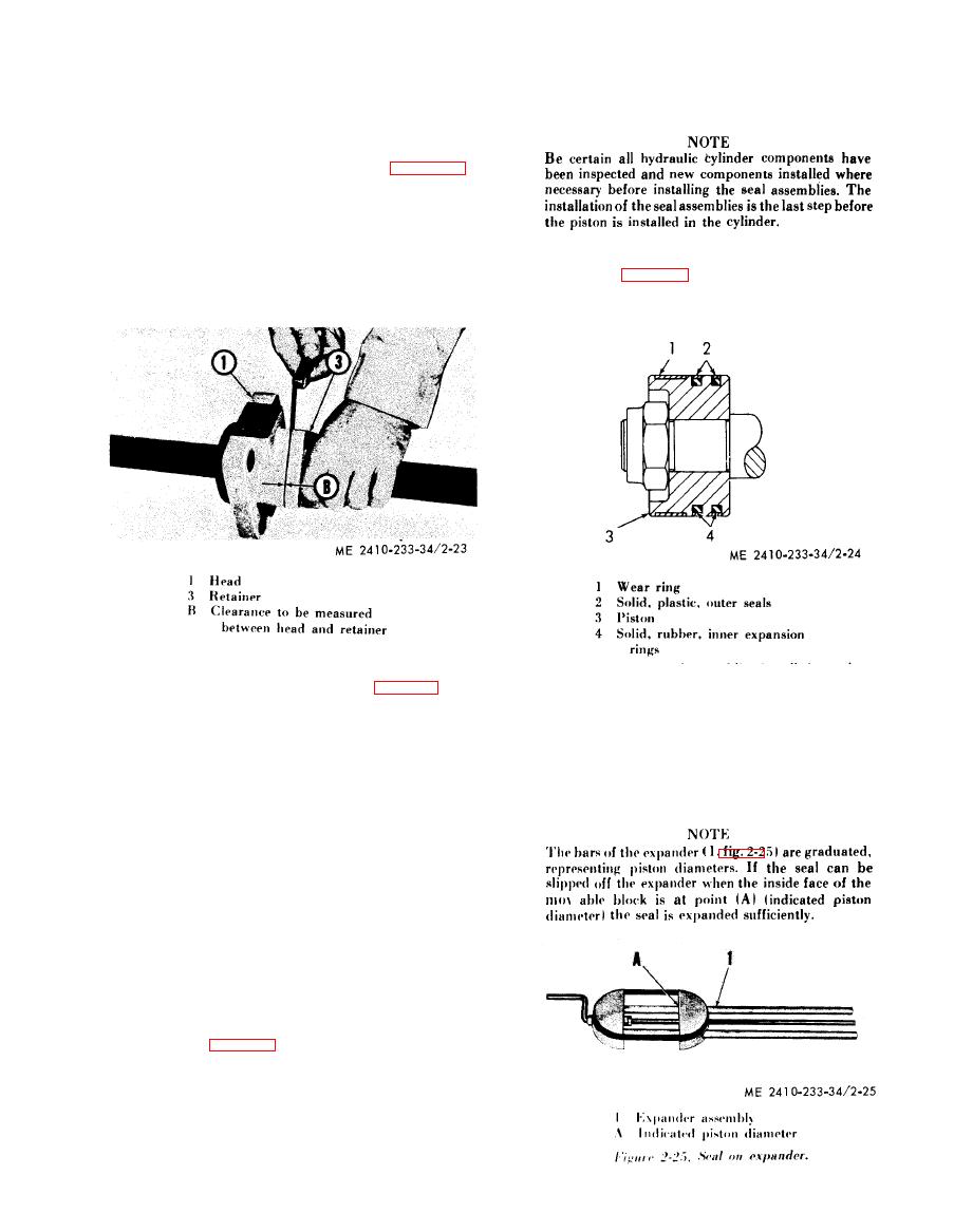
Figure 2-23. Measuring cylinder head clearance. |
|
||
| ||||||||||
|
|
 (b) Place the head on the rod and insert
c a l c u l a t e d by reducing the low figure 1/16 in. (1,5
one ring of packing at a time into the head.
m m ) and increasing the high figure 3/16 in. (4, 7
mm).
(c) Tap packing firmly into the head
w i t h the retainer (3).
(d) Hold retainer (3) firmly against the
packing and measure clearance (B, fig. 2-23)
between the retainer and the head with a thickness
g a u g e . Sufficient shims must be installed between
the retainer and head to obtain a total thickness of
.010 in. to .015 in. (2,54 to 3,81 mm) less than the
1. For ease of seal installation, remove the
measured clearance (B). The shims will preload the
wear ring (1, fig. 2-24).
packing properly
when
the
retainer
bolts
are
2. Install the inner expansion rings (4) on
tightened.
the piston (3).
(e) Remove the head (1, fig. 2-22) and
3. Measure the diameter of the piston to
c o n t a i n e d packing (2) from the rod (6). Install the
d e t e r m i n e the diameter to which the seal must be
correct amount of shims (5) and reinstall the head.
expanded. The outer seals of the seal assembly
CAUTION
must be expanded to a diameter slightly larger than
Be careful not to damage packing (2)
the diameter of piston to allow the seal to be placed
w h e n reinstalling head (1) on the rod.
o v e r the piston. Be careful not to over-expand the
(8) S o l i d s e a l a s s e m b l i e s .
s e a l s or they can be ruined.
(a) Each solid seal assembly consists of a
solid, rubber, inner expansion ring and a solid,
p l a s t i c outer seal. Since these seals are continuous
r i n g s (no split joint), special tools and procedures
a r e required for installation.
(b) T h e
following is a typical installation
procedure f o r
the solid seal assemblies. This
p r o c e d u r e can
be used for all hydraulic cylinders
w h i c h use the
solid seal assemblies. A piston may
h a v e one or two seal assemblies.
(C) The tools needed to install the outer seals
of the piston seal assemblies are: one Expander
Assembly (1, fig. 4-33). one Clamp Assembly (2)
( t w o clamp assemblies are required on the larger
diameter pistons), and one seal compressor (3).
M e a s u r e the diameter of the piston to select the
c o r r e c t seal compressor. C o m p r e s s o r s a r e m a r k e d
for nominal ranges. The actual usable range can be
|
|
Privacy Statement - Press Release - Copyright Information. - Contact Us |
