 |
|||
|
|
|||
|
Page Title:
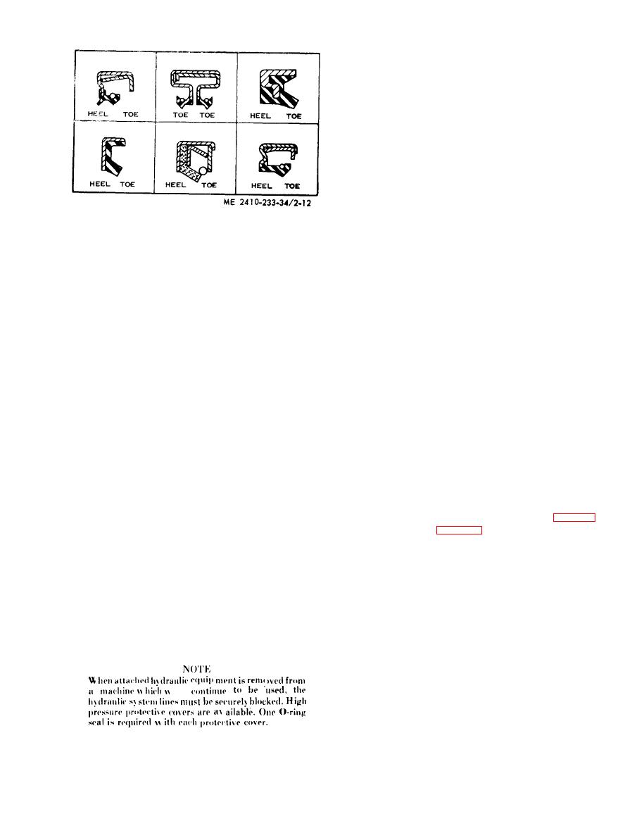
Figure 2-12. Heel and toe type seals. |
|
||
| ||||||||||
|
|
 (3) Sealing elements. Inspect all sealing
elements (O-rings, gaskets, etc.), when
disassembling and assembling hydraulic system
c o m p o n e n t s . Install new elements if necessary.
(41 H y d r a u l i c l i n e s .
(a) When installing metal tubes, tighten all
b o l t s finger-tight. Then, in this order, tighten the
b o l t s at the rigid end, the adjustable end, and the
m o u n t i n g b r a c k e t s . A f t e r the tubes are mounted,
install the hoses. Connect both ends of the hose
w i t h all bolts finger-tight. Position the hose so it
does not rub the machine or another hose and has a
m i n i m u m of bending and twisting. Tighten bolts in
both couplings.
(b) Due to manufacturing methods there is a
n a t u r a l curvature to a hydraulic hose. Install the
(c) Lubricate the lips of lip-type seals before
hose so any bend is with this curvature. In case of
i n s t a l l a t i o n . Use the same type lubricant in which
r e p l a c e m e n t hoses with angled-stem and reusable
the seal will be operating. Do not use grease on any
fittings, the hose curvature must be taken into
s e a l except a grease seal.
c o n s i d e r a t i o n when assembling and positioning the
(d) If, during installation, the seal lip must
pass over a shaft that has splines, a keyway, rough
angled stems.
surface or a sharp edge, the lip can be easily
(c) After the hoses are installed, follow this
damaged. Shim stock or other such material can be
procedure: With the diesel engine running, move
formed around the area to provide a smooth surface
the appropriate control levers to move the com-
o v e r which to slide the seal.
ponent to every possible position. Observe the hoses
m. Hydraulic Systems.
d u r i n g the cycle. Then lower the component to the
(1)
Cleanliness.
ground. Shut off the diesel engine and eliminate
(a) W h e n r e m o v i n g c o m p o n e n t s o f a
any twisting, rubbing and/or excessive drooping
hydraulic system cover all openings in both the
of hoses by rotating the stem of the hoses.
component and the machine.
(5) H y d r a u l i c f i t t i n g s .
(b) If evidence of metal or rubber particles
( a ) Fitting bodies with straight threads and
are found in the hydraulic system, flush the entire
O-ring
seals.
system.
1. This type of fitting is used in several
(c) Disassemble and assemble hydraulic
applications. The tube end of the body will vary in
components on a clean surface. Clean all metal
design depending upon the application. However,
parts in a nonflammable cleaning fluid. Then
the installation procedure of the fitting body into its
lubricate all components to aid in assembly.
mating boss will be the same. If the tube end of the
(2) Safety. Before servicing
the hydraulic
fitting body is as illustrated (either elbow (fig. 2-13)
system, NEUTRALIZE THE
HYDRAULIC
o r straight body (fig. 2-14)) a presetting procedure
PRESSURE.
i s necessary to assemble the sleeve onto the tube
PROCEDURE:
before connecting the tube to the end. See ( b )
(a) L o w e r c o m p o n e n t s t o t h e g r o u n d . I n
below.
some instances a removal procedure may require
2 . Place the nut, washer and seal as far
t h e component to be blocked in a certain position.
back on the fitting body as possible. Hold the
(b) With the engine shut off, move the
c o m p o n e n t s in this position and screw the fitting
i n t o its boss until washer just contacts the face of
h y d r a u l i c control levers to all positions to insure
the boss.
t h e r e is no pressure in the system.
(c) P l a c e a l l c o n t r o l l e v e r s i n H O L D
3. Place the fitting assembly in its correct
position.
angular position by turning the body out (coun-
t e r c l o c k w i s e ) , a maximum of 359. Tighten the nut
finger-tight.
ill
|
|
Privacy Statement - Press Release - Copyright Information. - Contact Us |
